SoutheastCon is an annual technical,
professional and student conference held by IEEE. The convention features
several competitions including a hardware competition in which teams build
robots that perform tasks autonomously. This competition will require that the
robot complete 4 different game related objectives and follow a white line
course in under 5 minutes. There will be 3 of these 5 minute rounds in which
the team can score points. Points are awarded for completing the games and
following the course. If there is a tie the victor will be determined by
whichever robot completed the course faster.
Team 1B’s robot will be able to recognize
the beginning of the game and engage in each of the four tasks to gain points
per round. The four tasks must be completed to gain points and may be played in
any sequence. The task are rotating one face of a Rubik’s Cube 180 degrees,
draw IEEE on Etch-A-Sketch, successfully play Simon’s says for 15 seconds,
lastly pick up one playing card and carry it across the finish line. A robot
that will be able to perform these tasks within the time limit will be
completed by March so that it may compete with Team 1A’s robot as well as the
Junior Team's robot.
The team will use the resources
provided by the college of engineering for advice, finance, meetings, and
presentations. The team is confident in completing a competing robot within the
budget and time constraints.
SoutheastCon will
be providing a flat black standard plywood with taped navigation lines as a
course for the robot. The location of the event will be at the Hilton Fort
Lauderdale Marina Hotel in Florida. It is assumed that the competition will be
held inside the Hotel which will exclude the any extreme weather conditions.
The design of the robot has been influenced by the operating environment, as
far as the materials used that will touch the surface. As well as following a
thin line taped onto a black flat plywood. There are some unknown factors such
as the temperature of the competition room and other small factors that are
irrelevant to the existing design.
Central Processing Unit
The microcontroller that will be used for the final project is the Arduino Due. There were many reasons for selecting this microcontroller including cost, performance and ease of use. At $40 the Due was reasonably priced enough that a second one could purchased in case one is damaged. Having a second Arduino also means that multiple people can be working different parts of the project at the same time. The Due was not the most powerful microcontroller out of the selection but it is more than powerful enough for this project. There are over 60 pins that can be used on the Due which means that can handle all of the interfacing needs of the project. This will include all of our different systems including the drive system and different servo configurations for different arms being used in this project. The Arduino is also an extremely popular microcontroller. It has a large array of tutorials, custom libraries and support available for use. By having these kind of resources available it means that there will be less time being spent learning how to use the microcontroller so more time can be spent in the design and testing phase of the project. Table 2.1b shows a more detailed overview of the microcontroller.
Table 2.1a - Overview of the Arduino Due
|
Operating
Voltage |
3.3 V |
|
Microcontroller |
AT91SAM3X8E |
|
Input
Voltage |
7-12V recommended |
|
Digital
I/O Pins |
54 with 12 being PWM |
|
Analog
Input Pins |
12 |
|
Analog
Output Pins |
2 |
|
Flash Memory |
512 KB |
|
Clock
Speed |
84 MHz |
Figure 2.1a - A top view of the Arduino Due
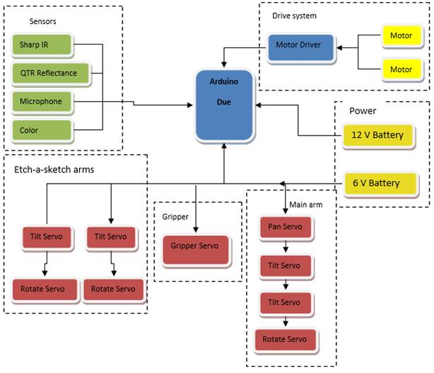
Figure 2.1b- Top level diagram showing all of the
different systems interfacing with the Arduino
Sensors
The sensors for the robot are what allows it to take in visual and
audio information from its surroundings, allowing it to follow the course and
play each of the games. Choosing simple and versatile options are a top
priority.
1.1.1 Line Following
The robot must be able to properly navigate along a white line, 0.94 inches wide, and cover it at all times. The sensor must be able to achieve this at various speeds and also recognize intersections.
Pololu QTR-8RC Reflectance Sensor Array - 10$
According to the product webpage- This sensor module has 8 IR LED/phototransistor pairs mounted on a 0.375" pitch, making it a great detector for a line-following robot. Pairs of LEDs are arranged in series to halve current consumption, and a MOSFET allows the LEDs to be turned off for additional sensing or power-savings options. Each sensor provides a separate digital I/O-measurable output.
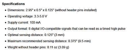
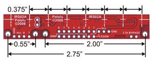
Figure 2.2.1a: QTR-8RC Reflectance Sensor Array Dimensions
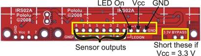
Figure 2.2.1b: Pin Connections on module
This sensor was chosen for multiple reasons. Its 8 independent outputs make it easy to cover more than the 0.94” line. The module can also be broken into two separate functional line sensors for additional coverage and accuracy. This can be used to recognize the “off” signal from the start LED. It also reads the position of a line and can be programed to correct itself. Its drawbacks are its small maximum sensing distance of 0.375” and its use of 9 I/O pins (1 extra for the LED).
Figure 2.2.1c: Module separated into two separate components
Figure 2.2.1d: Schematic diagram of the QTR-8RC reflectance sensor array
Sound Sensing
In order to play Simon, the idea is to use the sounds played for each of the four colored buttons in order to recognize the pattern. In order to achieve this, a microphone capable of recognizing the frequencies played by Simon will be necessary.
Sparkfun Electret Microphone Breakout
Figure 2.2.2a: Sparkfun Electret Microphone Breakout
Board w/ Pin connections
According to the product webpage - This small breakout board couples a small electret microphone with a 100x op-amp to amplify the sounds of voice, door knocks, etc loud enough to be picked up by a microcontroller’s Analog to Digital converter. The unit comes fully assembled as shown. Works from 2.7V up to 5.5V.
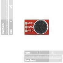
Figure 2.2.2b: Sparkfun Electret Microphone Breakout dimensions
The Sparkfun Electret Microphone Breakout board was chosen to pick up the sounds emitted from the Simon game. The general idea is to use a FIR filter designed via MATLAB to determine the various frequencies associated with the 4 colors of the simon game (red, blue, yellow, and green). The implementation will be discussed in further detail in section 3.4.3.
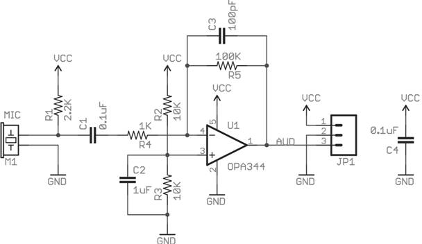
Figure 2.2.2c: Sparkfun Electret
Microphone Breakout Board Schematic
Figure 2.2.2d: Product Specification. Courtesy of Knowles Acoustics
Distance Sensing/Object Detection
In order to locate the games properly, some form of detection must be added. The sensor chosen will inform the robot of the game’s location relative to it. With proper response, the robot can continue to execute the proper game playing sequence with accuracy.
Since the order of the games will not change, a camera would have been over-designing. The chosen idea was to used two IR, optical range finders, to serve as the robot’s “eyes” , to detect its position relative to each game. A longer range sensor will be used to spot objects further away and slow down the motors. The smaller range sensor will be used to accurately get into position to precisely play each games.
Sharp GP2Y0A60SZLF Analog Distance Sensor 3V - 12$
From the product webpage - The GP2Y0A60SZ distance sensor from Sharp offers a wide detection range of 4″ to 60″ (10 cm to 150 cm) and a high update rate of 60 Hz. The distance is indicated by an analog voltage, so only a single analog input is required to interface with the module. The sensor ships installed on our compact carrier board, which makes it easy to integrate this great sensor into your project, and is configured for 3V mode.
Figure 2.2.3a: GP2Y0A60SZLF Analog
Distance Sensor w/ Dimensions
Feature summary
●
Operating voltage: 3V version: 2.7 V to 3.6 V
●
Average current consumption: 33 mA (typical)
●
Distance measuring range: 10 cm to 150 cm (4″ to 60″)
●
Output type: analog voltage
●
Output voltage differential over distance range: 3V version: 1.6 V (typical)
●
Update period: 16.5 ± 4 ms
●
Enable pin can optionally be used to disable the emitter and save power
●
Size without header pins: 33 mm × 10.4 mm × 10.2 mm (1.3″ ×
0.41″ × 0.4″)
●
Weight without header pins: 2.5 g (0.09 oz)
Figure 2.2.3b: GP2Y0A60SZLF Analog Distance Sensor
pinout
This sharp analog distance sensor has a range of 4”-60”, and will be used to first detect objects. It will allow the robot to slow its speed when within a certain range. Once it becomes closer than 4”, the smaller digital IR sensor will take over.
Figure 2.2.3c: GP2Y0A60SZLF Analog Distance Sensor Schematic Diagram
Sharp GP2Y0D815Z0F Digital Distance Sensor - 9$
From the product webpage - This small digital distance sensor detects objects between 0.5 cm and 15 cm (0.2″ and 6″) away. With its quick response time, small size, low current draw, and short minimum sensing distance, this sensor is a good choice for non-contact, close-proximity object detection, and our compact carrier PCB makes it easy to integrate into your project.
Figure 2.2.3d: GP2Y0D815Z0F Digital Distance Sensor w/ Dimensions
Feature summary
●
Operating voltage: 2.7 V to 6.2 V
●
Average current consumption: 5 mA (typical)
●
Distance measuring range: GP2Y0D815Z0F: 0.5 cm to 5 cm (0.2″ to
6″)
●
Output type: digital signal (low when detecting an object, high
otherwise)
●
Steady state update period: 2.56 ms typical (3.77 ms max)
●
Enable pad can optionally be used to disable the emitter and save power
(this feature requires you to cut a trace first)
●
Size without header pins: 21.6 mm × 8.9 mm × 10.4 mm (0.85″ ×
0.35″ × 0.41″)
●
Weight without header pins: 1.5 g (0.05 oz)
Figure 2.2.3e: GP2Y0D815Z0F Digital Distance Sensor pinout
This sharp digital distance sensor has a range of 0.2”-6”, and will be used for accurate detection of objects. It will allow the robot to precisely slow its speed, then eventually stop, when within a certain range. Once it becomes close enough, the robot will execute the proper game playing sequence.
Figure 2.2.3f: GP2Y0D815Z0F Digital Distance Sensor
Schematic Diagram
Arms/Servos
In order to complete the individual tasks, several mechanical appendages will be constructed to manipulate the toys. Several options for these robotic arms/grippers have been considered to find the best solution. The factors that went into consideration include compatibility, cost, and robustness.
![]()
 Grippers:
The design will include a gripping mechanism to hold all of the toys in
place. The grippers will consist of the
Little Gripper Kit from Lynxmotion (LGK)
and High Density Polyethylene (HDPE) cutouts to increase the range. The grippers open and close based on the
servos position. An appropriate servo
will be purchased and tested for system integration, preferably a standard cheap
servo like the HS-422. The LGK gripper
extensions will need to be designed and manufactured. The width of the LGK might become a problem
if the bottom chassis becomes cluttered and the grippers could become a
stationary pair of HDPE cutouts.
![]()
Main Arm
To complete the Rubik’s Cube challenge, Simon challenge, and the Playing
Card challenge, a large servo-controlled arm will cooperate with the sensors
and grippers. Grippers will hold the
cube in place while a main arm tilts down and twists the top layer of the
Rubik’s cube. The arm will be able to
pan and tilt by standard servos at the base.
Attached to the end of the mechanical arm is a rotating pair of tongs.
The tong shape will be positioned over the cube and a continuous rotation servo
will twist the top layer. Flat surfaces will catch the corners early and
produce a strong enough grip to twist the cube.
An adhesive will be placed on the inner brackets for the card challenge
instead of purchasing another arm. The
card must be secured and in usable condition in order to complete the
challenge.
![]()
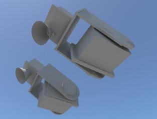
Etch-a-Sketch Arms:
The last challenge, Etch-a-Sketch, will have two additional mechanical arms with custom end-pieces to twist the knobs. Standard servos will be used for the tilt motion and the continuous rotation of the knobs. A subroutine will be used to draw the letters and complete the challenge. Two independent arms will shorten the time taken by manipulating both knobs instead of transitioning from one to the other. The Grippers will also hold the game in place.
![]()
![]()
Drive System
The drive system will be comprised of three major components working together in order to create all of the movements necessary for the robot’s navigation. The components are the Arduino Due, the Pololu A4990 Dual Motor Driver Shield for Arduino, and two DC brushed motors. The Arduino Due features 12 pins for PWM (pulse width modulation), which can be connected to the four pins (two for each motor) for motor control on the motor driver shield. The motor driver shield chosen is able to operate between 6V and 32V, and is capable of delivering 0.65 A to each motor channel. It is capable of regulating the current to the motors automatically (0.9 A peal), and protects the microcontroller from reverse-voltage, over-voltage, short-circuit and over-temperature conditions. The DC motors chosen operate at 12V, and the measured value for the current drawn while they are operational was found to be 0.3A, so the motor driver chosen is capable of providing enough power. The PWM frequency used by the driver has a minimum 17.3 kHz, with a max of 26 kHz, and a typical value of 21.7 kHz. The motor driver also has two diagnostic pins that are not necessary for its operation, but can be used to monitor the motor driver. The Arduino Due can be programmed using libraries available with the motor driver in order to change the speed and direction of each of the two motors (independently) to power this differential drive system. The line following system will determine the direction the robot needs to turn in order to follow the course, and will call the functions to set the motor speed/direction with the speed (positive value for forwards, negative value for backwards) as an argument.
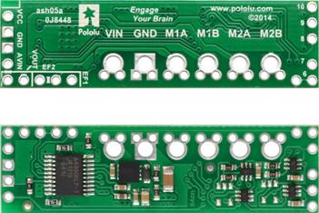
Figure 2.4a: A4990 Dual Motor Driver Shield for Arduino, Top and Bottom View
The motors chosen are 50:1
Metal Gearmotors with 64 CPR encoders, which can optionally be used in order to
provide feedback to the microcontroller about the velocity of and the distance
travelled by the motors to aid in navigation.
At 12V, the motors chosen have a no-load speed of 200 RPM, and stall
torque of 170 oz-in, which should be more than enough to move the robot at the
desired rate. The RPM and the wheel radius will allow for a max speed of around
1 m/s. The motors have already been purchased and are more powerful than necessary,
partially to account for potential situations in which the robot will be making
a slight turn and only be powered by only one motor. Additionally, in order to
ensure the balance of the robot with the current design, counterweight may be
added. The motors have been purchased, and at the time of the purchase the
weight estimate for the robot was unclear, so more powerful motors were chosen
in order to ensure that they would be adequate. With an estimate of 10 kg for
the mass of the robot, and 0.5 ft/s2 acceleration (half of the
desired velocity of 1 ft/s), along with the wheel diameter, an estimated torque
of 11.8 kg-cm was required for one motor to power the robot. This calculation
was done with the following equation, where the efficiency is 58% (68%
generally for DC motors, deducted an additional 10% to account for frictional
forces/other unknowns).
torque
= (mass)(acceleration)(wheel radius)(1/efficiency) (1)
If it is found that the motors are still too powerful, less powerful options
will need to be considered. .The motors will be connected to two Pololu 90x10
mm plastic wheels with silicone tires for grip. The wheels are attached to the
motors using a universal mount also by Pololu. A 1” plastic ball caster wheel
was chosen initially for the design, however this will more than likely be used
only for testing of the drive system. It will most likely need to be swapped
out for a sturdier option, currently in consideration is a larger ball caster
with a swivel bracket.
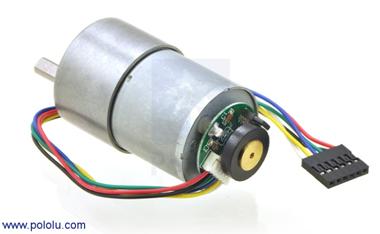
Figure 2.4b: 50:1 37D Metal Gearmotor with Encoder
The motors will be placed at the back of the robot, on the first layer of the chassis. The reason for this is that a lot of the robot’s weight will be in the back, and the two powered wheels will provide stability. Additionally, the mounts and servos for the arms to play the Simon Says game, and the grippers to hold the toys in place will take a lot of room in the front of the robot. Placing the motors in the back allows more room for these other components. The caster wheel will be placed in the front, a sturdier caster wheel may be chosen. Currently under consideration is a 2” stem and socket caster wheel shown below. One concern in choosing a caster with a swivel and a bracket is the wheel may need to turn around before actually turning, this would have to be considered in the programming for the system. The bracket may be necessary in order to support the weight of the robot, however.
Figure 2.4c: 2" Stem and Socket Caster Wheel
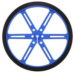
Figure 2.4d1: Pololu 90x10mm Plastic Wheels
With all of these components, and the 12V battery source for the motors, the drive system will operate as a differential drive system. The top level diagram for the system can be seen below.
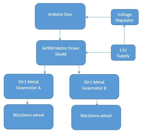
Figure 2.4e: Top Level Diagram for Drive System
Power Supply
With great consideration the team is convinced to have a power system of two NiMH Battery Packs. There will be two different power sources because of the different ranges of voltages need by the parts. While each part will require a different voltage source and the Arduino due will be used to supply voltage as well. Arduino built in voltage regulator it will be able to supply voltages to the parts with that were out too low compared to the two battery sources.
Nickel-metal hydride batteries NiMH have been chosen because their energy density approaches that of a lithium-ion cell. The only bad side to NiMH requires long periods of time to charge with a high self-discharge rate. Lithium-ion cell are leading currently in Power Capacities with because it has a zero memory less effect. NiCad stores less energy every time you recharge it and will take an extra steps to fully discharge to recharge.
The team has decided to purchase two power supplies in which one will
supply 12 V and the second will supply 6 V. The wheel motor and Arduino due
board require 12 V input to operate. Also the motors used in the ARMS/Grippers
will be using the 6 V power supply. The sensors operate at a smaller voltage
threshold hold and requires a voltage regulator to step the down voltage from
either voltage source. The Arduino Due board has a voltage regulator and will
be use to supply power to the sensors.
Table 2.5a: Different Battery Options
|
12 Volts |
Price |
Current Output (mAh) |
Weight |
|
NiMH Battery |
$29.95 |
|
997 grams |
|
6 Volts |
|
|
|
|
NiMH Battery |
$15.15 |
2200 |
142 grams |
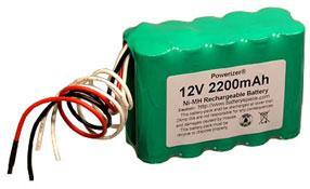
Figure 2.5a: Selected 12V Power Supply
Specs for 12V Supply
● Power Capacity 2200 mAh
● 10 (2x5) AA size 2200 mAh NiMH cells
● Power 26 Watts
● Weight 1 kg
● Discharging rate 2 A
● Charging rate 0.5-2.2 A
Discharging the battery pack below 10 V may damage NiMH. Leaving the ends of the wires uncovered; will allow the battery to improperly discharge. Power Capacity may be too close to the current being drawn upon startup of the drive motors.
The Arduino Due has an operation voltage range of 7-16V and the two drive motors also require 12 Volts to operate. The battery optimal voltage is rated at 14.5V falling in between both the Arduino Due and drive motors operating range. The battery is selected to overcome the current requirements at 12 Volts. The Arduino due and two drive motors were calculated to draw about 1400mA when used together. The battery has a large enough capacity to supply the robot with 1400mAh over one hour and a half. Each round is five minutes, giving more than enough of a large life span.
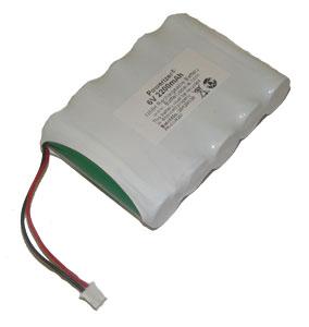
Figure 2.5b: Selected 6V Power Supply
Specs for 6V Supply
● Power Capacity 2200 mAh
● 6 Volts
● 5 (1x5) AA size 2200 mAh NiMH flat top cells
● Power 9.6 Watts
● Weight 0.14kg
● Discharging rate 2 A
● Charging rate 0.5-2.2 A
Discharging the battery pack below 6 V may damage NiMH. Leaving the ends of the wires uncovered will cause the battery to improperly discharge. The wires are too short as well and will need to be extended to provide better positioning on the chassis.
The servos have an optimal voltage range of 4.8-6 volts. The battery’s optimal voltage is rated at 7.1V falling in between both the Arduino Due and drive motors operating range. The total required current from all the servos is 1400mA giving the battery a longer life span off one cycle of charging. This was deeply desired by the group for multiple usage throughout three rounds with accurate performance.
The Arduino will act as the third power source providing the lower voltage to the sensors that operate in within the 3.3-5 volts. The voltage will actually be specified through coding to power each pin assigned to the sensors.
Voltage Regulator
The voltage regulator has a lower efficiency rate, supplying voltage at efficiencies ranging between 80-90%. This will supply the sensors with a small amount of current, potentially not allowing the sensors to operate properly
The team has decided to go with one charger that will supply charge to both batteries to the cut the cost, eliminating the need to buy a charger for each power source. This gives more room in the budget to buy more power supplies (back-up batteries) to cut down on the need for charging in-between rounds. It is proposed to purchase one spare battery for each source. The charger is priced at $16.95 and is capable of charging batteries between the ranges of 6-12 V. This charger will be able to fully charge each battery within four hours.
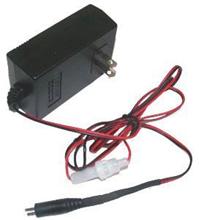
Figure 2.5c: Image of Selected Charger
In the event that the method for connecting the driver motors is changed, the male jumper can be cut off and the wires can be plugged into a breadboard or soldered to manually configure it.
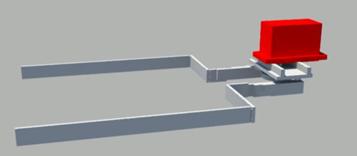
Chassis
The chassis will be a two layer chassis, made of cut HDPE. The top layer of the chassis will be used to hold the main arm, as well as the batteries for the robot. The bottom layer will hold breadboard, the DC brushed motors, the Etch-A-Sketch arms and motors, the grippers and the line following system. A 3D model of the empty chassis can be seen below in Figure 2.6a, and another view with component placements can be seen in Figure 2.6b.
The robot will include two rear wheels with motors, and a caster wheel in the front for support. A line reflectance sensor array will be placed close to the rear wheels to ensure more accurate turns around the course. Another, smaller IR sensor will be placed towards the middle to detect the start LED and also double as a line follower. In front of the caster should be the object detector, used to see objects directly in ahead of the robot. The main arm, side arms, and grippers will be mounted at the front to simplify locating and playing games. The power supply and processor will be placed on the back and double as a counterweight to the components in the front. The components in the 3D diagrams used in this report will be color coded according to Table 2.6.
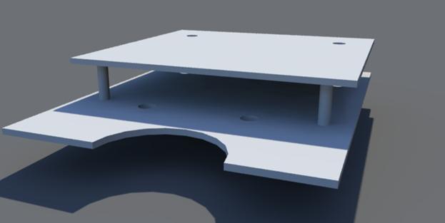
Figure 2.6a: Empty Chassis 3D Model
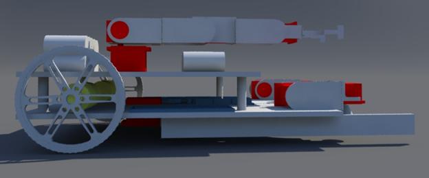
Figure 2.6b: Chassis Model with Components
Table 2.6: Color Coding for 3D Diagrams
|
Color |
Significance |
|
Red |
Servo |
|
Green |
Sensors |
|
Yellow |
Motors |
|
Blue |
Circuits/Microcontroller |
Design of Major Components/Subsystems
Overview

Figure 4.1a: Top Level System Design Block Diagram
The team has agreed on a well-balanced robot. It is proposed that the robot will drive across the course using an ideal speed covering all untraveled taped course. Sensors will be used to follow the course line, start the robot based off of IR sensors, and detect sound to play a Simon, and measure distance from games. The autonomous robot will be discerning enough to recognize each game secure it with the grippers and manipulate each using the arms designated for them. The robot intelligence will also ensure its accuracy in manipulating the games to gain maximum points. The robot will be programmed to finish the four tasks as fast as possible within a five minute time limit. The robot will play three rounds and must have enough power to last all three. NiMH batteries were chosen because of their large battery capacity in theory if fully charged the NiMH batteries can withstand three rounds. The team has decided to bring fully charged spare batteries for the competition as well as the charger. The robot will have two NiMH batteries with different voltages and the Arduino board will be used to power the sensors using low voltages.
Central Processing Unit
The microcontroller being used for this project is an Arduino Due. There are 12 pins for pulse width modulation (PWM). These pins will be reserved for the servos and the DC motor control. These pins, which are numbered 2-13, can be seen on the right side of Figure 3.1a. Depending on which type of servos are eventually purchased an analog to digital converter may be needed to be put in between the servo and the PWM pins. This microcontroller operates at 3.3v so there will need to be a voltage regulator in between the motors and the microcontroller to ensure that board does not get damaged.
Figure 3.1a - Arduino Microcontroller and PWM pins
The QTR-8RC reflectance sensor will be used for line following. This sensor requires 8 digital I/O pins. It will be connected to pins 22, 24, 26, 28, 30, 32, 34, 36, 38. These pins all sit next to each other as seen in Figure 3.1a. Having all of the reflectance sensor pins in a row allows for easier management. The color sensor for determining whether the start LED is on or off also require a digital I/O pin. This can be placed on pin 52 to differentiate from the reflectance sensor pins.
Most of the pins being used on the board will be digital pins of some kind but there are a couple of analog pins being used. There will be 1 analog input pin, A0 that will be used for the microphone. The microphone will be used for determining what note is being played in Simon Says. By figuring out what pitch is being played the Arduino can tell the appropriate servos to turn and click the corresponding button on the game. The gripper servo will be connected to an analog output pin, DAC0.
 Figure 3.1b - Flow chart showing how the code will
branch
Figure 3.1b - Flow chart showing how the code will
branch
Programming will be an integral part of this project. The flowchart in Figure 3.1b shows a brief overview of the code will be broken up and worked on. First there will be an initial branch of code calling all of the proper libraries and setting up some known variable such as the different servos. This will be done in 2 different files which will be a games.h file and a main.cpp file. The main.h file will have the code for line following, object detection, detecting the start and what the robot should do once it passes the finish line. All of the game functions will also be called in the main.cpp file. The games.h will have the definitions for the game functions. So the actual servo movements and controlling will be done inside of the games.h file while the main.cpp simply calls whichever game function is needed at the time. These two files will be consist of the initial branch. There will be different branch for each game coming off of the games.h file. So each game function will be constructed independently of each other. Here the main priority will be getting the servo movements working under perfect conditions. For example the Etch-a-Sketch function will have the servos spins so that IEEE is written on the Etch-a-Sketch. A separate branch will be made for the main.cpp file where the line following and game detection will be initially worked on. Once this first section of the main.cpp and a single game function is finish the two files will be combined and tested. So the robot will show that it can clearly follow a line, find a game and play it correctly. As more game functions are completed they will be added to the main branch one by one. By the time all of the branches are added the robot should be able to adequately start by itself, follow a line, detect and correctly play all 4 games and cross the finish line. The only thing left to do with the code once the main branch the only thing left to do with the code is try to make the code smaller and have the robot complete the games faster.
Drive System
Microcontroller, motor driver shield and DC motor integration
The Arduino Due microcontroller will be used for sending digital signals to the
motor driver shield. There are twelve pins on the MCU with pulse width
modulation, four of these will be used to connect to the motor driver shield,
two for each motor. The A4990 Dual Motor Driver Shield for Arduino was created
specifically with the use of Arduino microcontrollers in mind, designed to
connect directly to the board and use the libraries already written for the
Driver Shield, which have explicitly been tested with the Arduino Due. It was
designed specifically for the application of controlling two higher voltage DC
motors. The driver itself is powered by the Arduino, using the 5V output and the ground. The power
source for the motors is connected directly to the driver shield. There are two
connections for each motor, M1A, M1B, M2A and M2B, which are connected to the
red and black wires (power and ground) of the motors. The connections for the
system can be seen in the figure below. There is an additional pin for monitoring
the driver, but it is not mandatory to be placed on one of the PWMs and can be
placed in any other MCU pin formatted for input.
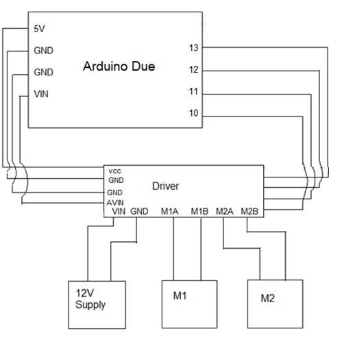
Figure 3.3a: Pin Connections for Drive System
There are libraries available to work with the motor driver
shield, along with the pins on the Arduino Due capable of using PWM, on the
website it was purchased from. These libraries allow for the motors’ speed and
direction to be controlled with code such as the example code that is included
below. The line following system would call the function for each motor with a
single parameter- the desired speed.
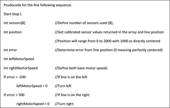
Psuedo Code for Drive System
Void SetMotor1Speed
(int speed)
{
Init()
boolean
reverse ß 0
if
(speed < 0)
speed ß -speed
reverse ß 1
if
(speed > maximum speed)
speed ß maximum speed
#ifdef
A4990MOTORSHIELD_USE_20KHZ_PWM // defined in libraries, send //speed
to motor
OCR1A
ßspeed
#else
analogWrite
(_M1PWM, speed * 51/80)
//
case for if either speed was negative (exclusive) or _flipM1 was active
If
(reverse xor _flipM1)
digitalWrite (_M1DIR, HIGH)
else
digitalWrite (_M1DIR, LOW)
}
The same code applies for motor two, swapping out M1 for M2. Feedback from the line following system would determine the speed, and from its sign, the direction (the variables speed and reverse in the code), a table below depicts this. The variable “reverse” is 1 for the backwards direction of the motor. Additionally, a timing diagram for the input/output of the motor driver shield can be seen below for the various functions.
Table 3.3: Variables for Drive System Operation
|
Operation |
M1 speed |
M1 reverse |
M2 speed |
M2 reverse |
|
Left Turn |
0 |
0 |
speed > 0 |
0 |
|
Hard Left Turn |
speed > 0 |
1 |
speed > 0 |
0 |
|
Right Turn |
speed > 0 |
0 |
0 |
1 |
|
Hard Right Turn |
speed > 0 |
0 |
speed > 0 |
1 |
|
Forward Drive |
speed > 0 |
0 |
speed > 0 |
0 |
|
Backward Drive |
speed > 0 |
1 |
speed > 0 |
1 |
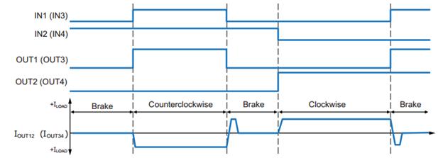
Figure 3.3b: Timing Diagram for Brushed DC Motor Input and Output Sequence
Sensors
The sensors for the robot are split into 4 different categories: starting, line following, microphone for Simon, and object detection. All sensors proposed are fairly cheap and simple to implement, making replacement a good possibility for a contingency plan.
Starting LED Sensor
The robot must begin in a white 1’x1’ square and detect the shut off signal of a visible flush red LED. In order to achieve this, the QTR-8RC reflectance sensor array will be split into two separate components. The smaller module, with 2 phototransistors, will be placed around the midpoint of the robot. With the optional help of a light filter, the array will recognize the off signal and alert the processor by detecting a change in the light. The robot will then move forward, about a foot, and then begin to navigate the course.
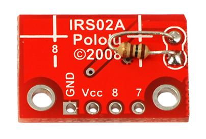
Figure 3.4.1a: Included Resistor Soldered to make the smaller module functional
When broken into two separate components, the QTR-8RC reflectance sensor will also serve as the start LED detector. It will be place underneath the first level and in the middle to be positioned correctly to detect the shut off signal.
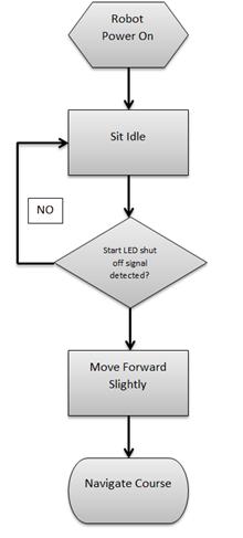
Figure 3.4.1b: Sequential Block Diagram for Start
Line Following
The robot must navigate a 0.94” white line varying each round. The larger module (6 sensor array) of the QTR-8RC will be used to accomplish this task. It will be placed near the rear, by the motor controlled wheels, for accurate turns. The risk of detecting the white block late, due to the position of the sensor, should not pose a problem because the games will/ are allowed to be move to the very front of each playing zone. It will also be able to detect intersections and other complex course structure until it reaches the finish point.
Figure 3.4.2a: Competition Course
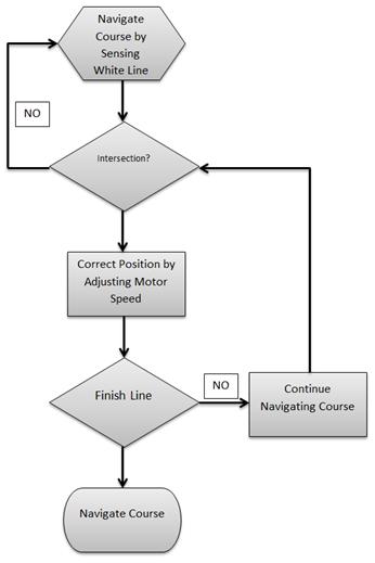
Figure 3.4.2b: Sequential Block Diagram for Line Following
The sensor’s 8 outputs will be connected to 8 digital pins of the processor. The sensor’s LED output will also be connected to a digital pin and serve as an indication during calibration.
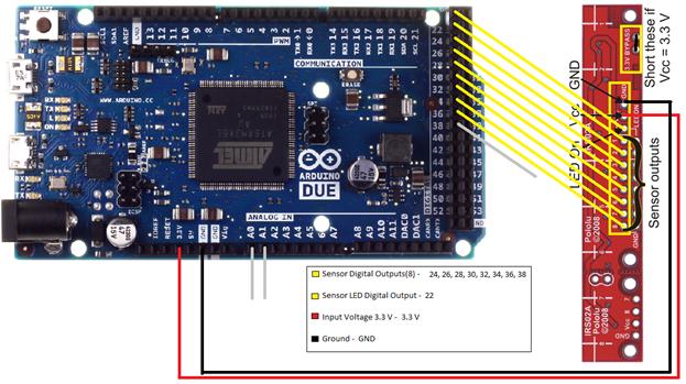
Figure 3.4.2c: Pinout for Line Following
Microphone for Simon
The robot must first correctly play Simon for 15 seconds. Using a microphone was decided to be ideal for this task. It will be placed on the main (pan & tilt) arm to accurately measure the frequency of the various Simon sounds. The signal will then be used to determine which button the robot must correctly press.
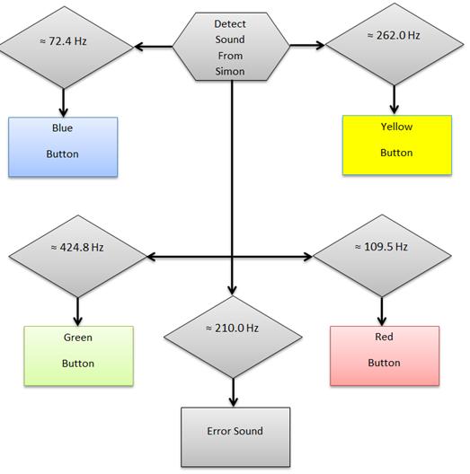
Figure 3.4.3a: Sequential Block Diagram for Microphone
Using the fdatools in MATLAB, filters will be designed with C headers containing the coefficients necessary to implement the filters. These will be used to distinguish between the different frequencies, and allow the robot to properly recognize with button on Simon was activated. The robot will then act accordingly based on the button’s sound.
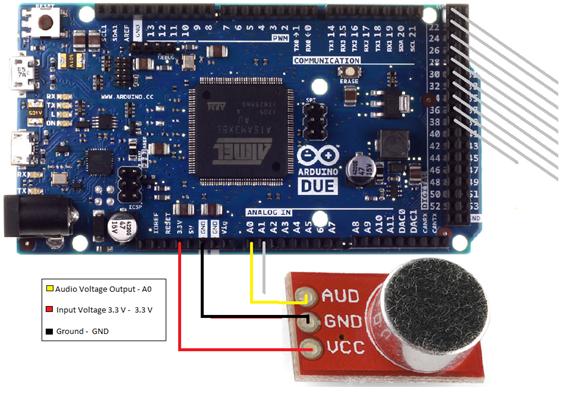
Figure 3.4.3b: Pinout Diagram for Microphone
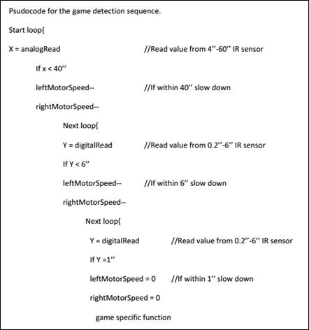
Object Detection
The robot must locate each game within a 1’x1’ white square. The team decided to use two optical range sensors to complete this task. The sensors will be located on the front of the robot; as low as possible to detect all games. It will send a signal to the processor to slow down, stop, and then start a game specific sequence whenever the robot comes within a certain range.
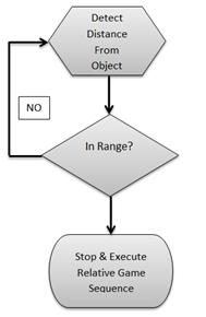
Figure 3.4.4a: Sequential Block Diagram for Object Detection
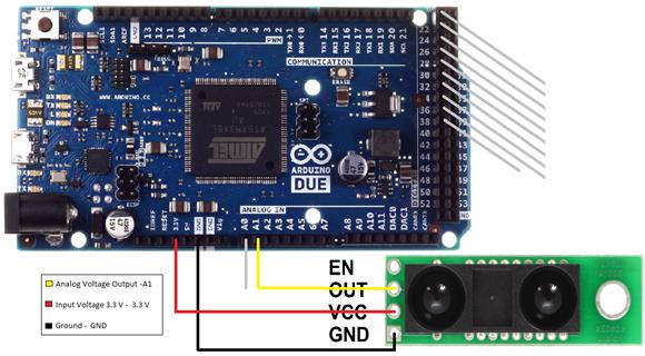
Figure 3.4.4b: Pinout Diagram for 4”-60” Analog IR sensor
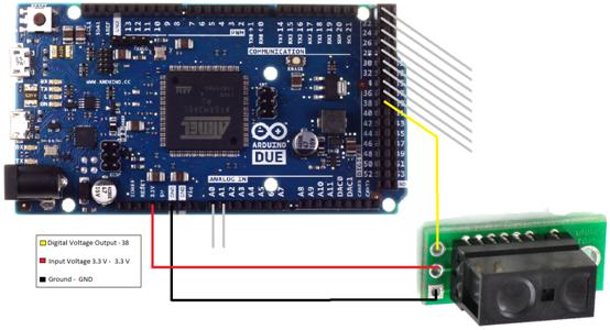
Figure 3.4.4c: Pinout Diagram for 0.2”-6” Digital IR sensor
Servos/Arms/Grippers
The proposed design for the mechanical arms is largely centered on programming servos. The servos create all of the movements for the arms and grippers. Sequential programming will instruct the servos to position joints and end pieces to perform the toy challenges. The servos selected for the arms are controlled by Pulse Width Modulation and powered by 6V NiMH battery pack. A power distribution circuit will be used to amplify the current output of the battery pack and to ensure the servos receive the correct current.
HS-422:
The first selection for servo motors is the HS-422. It is standard sized and will be used for a lot of motions in the mechanical arms. It is extremely affordable and the maximum torque is 30x its weight making it strong enough to hold and place the mounts in place.
Table 3.5a: HS-422 Specifications
|
Required Pulse |
3-5 Vp-p Square Wave |
|
Operating Voltage |
4.8-6.0 Volts |
|
Operating Speed |
0.16sec/60° at no load |
|
Maximum Torque |
56.93 oz-in. (4.1kg-cm) |
|
Weight |
1.6oz (45.5g) |
![]()
Figure 3.5b: HS-422 location in the main arm (top), etch-a-sketch arms (bottom left), and grippers (bottom right)
HSR-1425CR:
The HSR-1425CR servo is a standard servo modified for continuous rotation. The servo is fairly robust and will be used to rotate the Rubik’s Cube.
![]()
 Table3.5b: HSR-1425CR Specifications
|
Required Pulse |
3-5 Vp-p Square Wave |
||
|
Operating Voltage |
4.8-6.0 Volts |
||
|
Operating Speed(6.0V) |
52 RPM at no load |
||
|
Maximum Torque(6.0V) |
42 oz-in. (3.1kg-cm) |
||
|
|
Figure 3.5d: HSR-1425CR location
in the main arm |
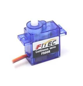
FS90R:
The FS90R is the smallest servo that is manufactured specifically for continuous rotation. It has great speed and torque for its size. It will be used to rotate the Etch-a-Sketch cones.
![]()
|
Required Pulse |
3-5 Vp-p Square Wave |
|
Operating Voltage |
4.8-6.0 Volts |
|
Operating Speed(6.0V) |
130 RPM at no load |
|
Stall Torque(6.0V) |
20.8 oz-in. (1.5kg-cm) |
|
Weight |
0.317 oz (9g) |
Table 3.5c: FS90R Specifications
Figure 3.5f: FS90R location in the etch-a-sketch arms
Below is a recording of the servos rotating in both directions. A DC power supply and function generator is first used. The 6V NiMH battery pack and an Arduino were later incorporated for system integration.
https://www.youtube.com/watch?edit=vd&v=i0wzq2yvNc4
![]()
![]()
Table 3.5f: Pseudo Code for Servos
|
Rubik’s Cube |
Simon |
Etch-a-Sketch |
Playing Card |
|
Self-Align |
Self-Align |
Self-Align |
Self-Align |
|
Close Grippers |
Close Grippers |
Close Grippers |
Align Main Arm |
|
Drop Main Arm |
Drop Main Arm |
Drop Cones |
Drop Main Arm |
|
Align Main Arm |
Subroutine for Simon a) Extend, Rotate(cw), and Drop for RED b) Extend, Rotate(ccw), and Drop for GREEN c) Contract, Rotate(cw), and Drop for BLUE d) Contract, Rotate(ccw), and Drop for YELLOW |
Subroutine for Etch-a-Sketch i)Twist Left Cone for Left/Right ii) Twist Right Cone for Up/Down |
Lift Main |
|
Rotate End-piece |
Lift Main Arm |
Lift Cones |
|
|
Lift Main Arm |
Open Grippers |
Open Grippers |
|
|
Open Grippers |
|
|
|
General Coding
Information
Using the Arduino software to program the MCU and control the servos. The Arduino Due board has 12 digital PWM ports that automatically generate the correct signal to control servos. The function analogWrite(pin,value) will be utilized to position servos and mounts. Another technique would be to "manually" implement PWM on any pin by repeatedly turning the pin on and off for the desired times. Example shown below
void setup()
{
pinMode(13, OUTPUT);
}
void loop()
{
digitalWrite(13, HIGH);
delayMicroseconds(100); // Approximately 10% duty cycle @ 1KHz
digitalWrite(13, LOW);
delayMicroseconds(1000 - 100);
}
Power Supply
The team will manufacture a housing case to secure to the chassis near the rear end of the robot. The placement of the batteries also will aid in balancing robot’s weight. One battery will power the robot’s central processing unit and drive motors. While the other battery will power the motors used to control the arms. Lastly the voltage regulator will step-down the incoming voltage to two different voltages for sensors requiring lower voltages.
Two chargers will be purchased with capability to charge both NiMH batteries. Batteries will be tested and calculated to an accurate full charge time. Data will be use to devise a charging schedule to prepare the batteries before every use. Also data and observations will be used to determine how many spare batteries are necessary. The spare batteries are being considered for back to back use, playing three consecutive rounds.
Pin Connections:
The team has decided to use to breadboards, one for each battery and the components connected to them. The 12 volt battery will supply voltage to the positive voltage bus on the breadboard(1) allowing the Arduino and drive motors to connect to the 12 V simultaneously. The current calculated from the torque for each drive motor is 299.53mA. The stall current is rated at an alarming 5A this will only be a problem when starting up at full power. To overcome this set back a H-bridge will be use to control the voltage sent to the drive motors. Through coding the motors will receive a low voltage to allow a slow take off increasing friction and traction of the wheels. The equations used to calculate the current drawn from the current is displayed below using the given values.
The torque calculated previously was 11.8 kg-cm, with the
absolute maximum estimated weight of, 10kg speed of 0.3048 m/s (1 ft/s), and acceleration
of 0.1524 m/s2.
![]() (2)
(2)
![]() (3)
(3)
Contingency Plan:
The price of the batteries and chargers are low enough to purchase more when needed. Having a spare of batteries cuts idle time. If system was to fail during the competition alkaline batteries will be purchased and used to build a replacement power source.
Table 3.6a: Power Consumption for Motors and Arduino
|
Battery |
12 Volts |
26.4 Wh |
|
2200mAh ( Capacity) |
|
Item |
Description |
Quantity |
Volts (V) |
Current (mA) |
|
50:1 Metal Gearmotor 37Dx54L |
Wheel Motor |
2 |
12 |
600 |
|
Arduino Due |
Microcontroller |
1 |
12 |
800 |
|
Total |
|
3 |
12 |
1400 |
Figure 3.a: DC Motors and Arduino Battery Connections
Table 3.6b Power Consumption for Servos
|
Battery |
6 Volts |
9.6Wh |
|
2200mAh |
|
Item |
Description |
Quantity |
Volts (V) |
Required Current (mA) |
|
HS-422 |
Standard Servo |
5 |
4.8-6 |
750 |
|
FS90R |
CR Micro Servo |
2 |
4.8-6 |
400 |
|
HSR-1425CR |
CR Standard Servo |
1 |
4.8-6 |
100 |
|
HS-85BB |
Micro Servo |
1 |
4.8-6 |
240 |
|
Total |
|
9 |
4.8-6 |
1490 |
Figure 3.6b Servo Motors Battery Connections
Table 3.6c: Sensor Power Consumption
|
|
|
|
|
|
||||
|
Item |
Description |
Quantity |
Volts (V) |
Current (mA) |
||||
|
Micro Phone |
Sensor |
1 |
2.7-5.5 |
0.5 |
||||
|
Analog Distance Sensor |
Sensor |
1 |
2.7-3.6 |
33 |
||||
|
Digital Distance Sensor |
Sensor |
1 |
2.7-6.2 |
5 |
||||
|
QTR-8RC Reflectance Sensor |
Sensor |
1 (8 in pack) |
3.3-5 |
200 |
||||
|
Total |
|
4 |
|
238.5 |
||||
Figure 3.6c: Sensor Battery Connections
Chassis
The Chassis is the backbone for the robot, it will provide protection, stability and support for the system. The team agreed to use a two level chassis in order to distribute the weight evenly throughout the robot as well as space out the different components to maximize wiring space.
Top Level of Chassis
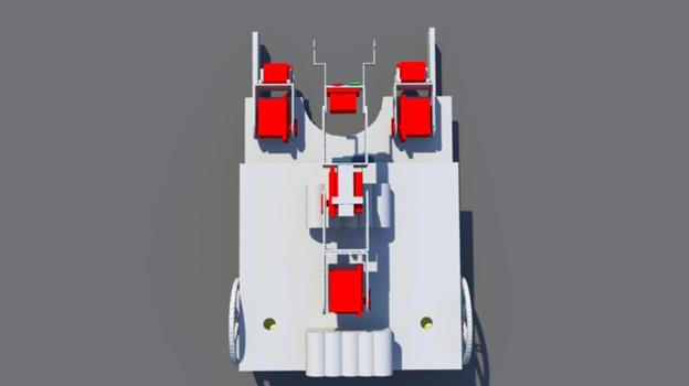
Figure 3.7a: Chassis Top Layer
The top level of the chassis will support the both the 12 V and 6 V batteries. The diagram above depicts a clear visual of the design, the two holes will be use to send down the wires from the batteries to their respective breadboards. The top level of the chassis has the main purpose of freeing up space on the bottom level for wiring, the DC drive motors, and weight distribution. The weight of the overall robot will be a major factor when stopping and taking off. The goal is to distribute the weight throughout the robot evenly such that there does not need to be additional sections in the code to ensure that the robot does not tip over when turning, starting or stopping. As seen in Figure 3.7a above, the main arm and the batteries are placed on the top layer.
Bottom Level Chassis
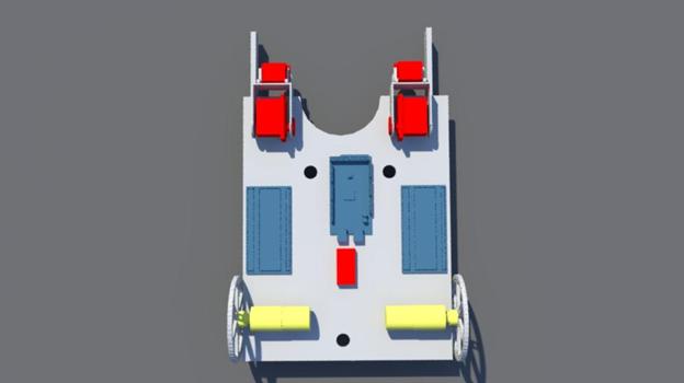
Figure 3.7b Bottom Layer of Chassis
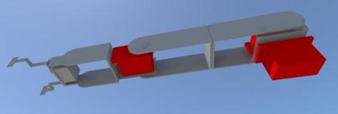
As seen in the figure above, the DC drive motors and wheels are attached to the bottom layer of the chassis, along with the breadboards, microcontroller, arms for Etch-A-Sketch and the grippers. A more clear view of the grippers can be seen in the complete side view of the chassis below.
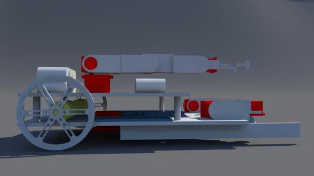
Figure 3.7c: Side view of Complete Chassis