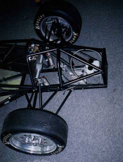
2000 Model Formula Suspension
|
Part #
|
Qty
|
Item
|
Part #
|
Qty
|
Item
|
|
1
|
2
|
Rockshox
|
18
|
6
|
5/16 AN Flat Washers
|
|
2
|
2
|
Upper A-Arms
|
19
|
6
|
¼ Lock nuts
|
|
3
|
2
|
Lower A-Arms
|
20
|
2
|
5/16 Lock nuts
|
|
4
|
6
|
Right Hand Rod Ends
|
21
|
2
|
#10 Aluminum Spacers
|
|
5
|
4
|
Nylon Washers
|
22
|
2
|
3/8 ID Needle Bearings
|
|
6
|
2
|
Push Rods
|
23
|
2
|
#10 ID Polished Rods
|
|
7
|
6
|
10-32 Allen Head Bolts
|
24
|
4
|
Rockers Plates
|
|
8
|
6
|
#10 Lock Washers
|
25
|
2
|
Needle Bearing Cases
|
|
9
|
6
|
#10 Flat Washers
|
26
|
4
|
Spherical Bearing Retaining rings
|
|
10
|
8
|
5/16 Spacers
|
|
|
|
|
12
|
24
|
¼ Spacers
|
|
|
|
|
13
|
14
|
¼-28 grade 5 Bolts
|
|
|
|
|
14
|
4
|
¼ ID Spherical Bearings
|
|
|
|
|
15
|
4
|
5/16 ID Spherical Bearings
|
|
|
|
|
16
|
2
|
Left Handed Rod ends
|
|
|
|
|
17
|
28
|
¼ AN Flat Washers
|
|
|
|
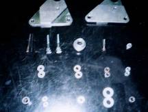
Table 1: 2000 Model Formula Suspension Parts List
Table 1
is a list of parts. The simple part number
assignment can be used to order new parts from your local Formula Suspension
dealer.
2 – 7/16 Box End Wrenches
1 – 5/16 Wrench
Inch-pound Torque Wrench (50-230 in-lb range)
1 – 5/16 Socket
2 – ½ Box End Wrenches
5/32 Allen Wrench
1 – 7/16 Socket for the Torque Wrench
1 – ½ Socket for Torque Wrench
Needle Nose Pliers
Flat Head Screw Driver
21mm Lug Wrench
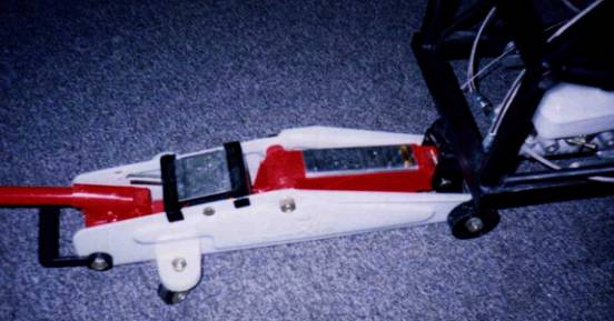
Floor Jack
3/8 Wrench
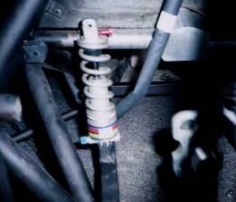
The
ride height is adjusted using the pre-load adjusters on the Rock Shox
spring/damper units. If the car’s
weight is balanced laterally then each of the shocks must have the same
pre-load. This means that you have to
count the number of turns you make with the pre-load adjusters.
Steps for adjusting
ride height:
1.
With the intended driver in the car measure the height.
2.
Jack up the front of the car until the wheels are just about
off of the ground to unload the springs.
3.
Tighten or loosen the adjusters both the same amount of turns
on each shock.
4.
Lower the jack then measure the height.
5.
Repeat 1-4 until the height is correct.

·
The spherical and rod end mounts should be lubricated
with lightweight oil prior to each drive.
To lubricate them merely squirt the oil on the ball surface.
·
Oil in the shocks should be changed manually. Take them to your local bicycle pro shop to
get it changed.
·
The nitrogen charge in the shocks needs to be check and
or recharged annually also. Your local
motorcycle shop or bicycle pro shop should do this.
·
The bearings in the rockers should be removed cleaned
and re-greased regularly.
·
If the suspension is ever disassembled, the alignment
needs to be checked and the camber needs to be reset.

1.
Place the car on a flat, level surface.
2.
Place a jack under the front of the car and carefully jack the
front of the car up until the wheels are about a quarter of an inch off of the
ground.

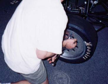
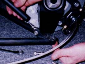
3.
Remove the lug nuts and slide the tire off of the car.


4.
Locate the 5/16 a-arm to upright mounting bolt on the
underside of the upright.
5.
Using a ½ inch wrench remove the 5/16 bolt. This will detach the lower a-arm from the
upright. Care should be taken so that
the upright doesn’t slide off and fall.


6.
Locate the 5/16 bolt on the top of the upright
7.
Remove the 5/16 bolt and lay the upright to the side. Be careful not to bend any of the steering
components or crease the brake line, as they will still be attached.

8.
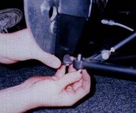
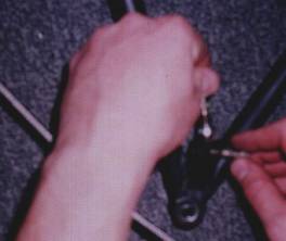
Locate the lower and upper push rod jam nuts.
9.
Using a 7/16 wrench loosen both of these. Be aware that one of the two nuts will be
left handed thread and thus it will have to be loosened the other way. Silver rod ends are right handed. Gold ones are left-handed.
10.
Support the bottom A-arm with light pressure with your hand to
prevent it from falling. Twist the push
rod in the direction that makes it extend in length until the rod ends fall out
of it.
11.
Using a 5/16 and ½ wrench loosen and remove the bolt for the
lower push rod, rod end. Be careful not
to lose the spacers.
12.
Also remover the bolt for the upper push rod, rod end. Again, keeping track of the spacers.

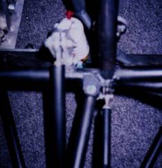
13.
Locate the rocker mounting bolt.
14.
Remove the rocker mount bolt and pull the rocker assembly out
of the mount.


15.
Locate the shock mount bolt.
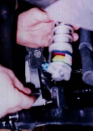
16. Using a 5/32
Allan wrench and a 3/8 wrench. Loosen
then remove the bolt and slide the shock out of the mount.


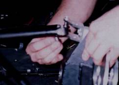
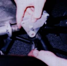
17.
Locate the A-arm
mounting bolts.


18. Using two 7/16
wrenches, loosen the mounting bolts, remove them then slide out the ends of the
A-arms. Be careful not to lose the
spacers.

18.
Support the outer A-arm with the outer spherical bearing open
below and, using a socket and a hammer tap on the spherical bearing until the
retainer ring falls out.
19.
Continue to tap until the bearing falls out.
20.
To remove the upper inner spherical bearings support the end
of the A-arm so there is open space below the spherical bearing and lightly rap
on the bearing with a socket until it falls out. It is important that the socket is applying pressure on the
outer race of the bearing only.

21. To remove the
rod ends from the lower A-arm, loosen the jam nut and rotate the rod end.
21.
Using the 5/32 Allan wrench and a 3/8 wrench remove the rocker
plates securing bolt.

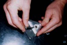
22. Remove the nylon
washers from the sides of the bearing case.
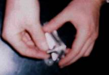
23.
Remove the polished
rod.
24.
Then the rocker plates can be separated from the bearing
housing.
To
reassemble the suspension reverse the assembly process and adhere to the
following assembly notes and torque charts:
·
If the bearing in the rocker is fowled then a new
bearing case, bearing and polished rod must be purchased as they are not
serviceable and are precision sets.
·
All of the bolts must be torqued according to the following
torque chart.
·
The lock nuts are not reusable. The must be replaced with each removal.
·
Before inserting the polished rod into the rocker
assembly, make sure to completely remove any dirt and debris from the inside
the bearing and bearing case. Then
lubricate the needle with standard EP grease.
·
Be sure not to scratch the polished rod.
·
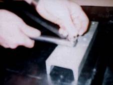
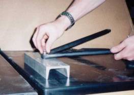
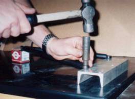
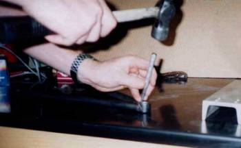
Install the spherical bearings in the A-arms using a
socket and a hammer or preferably a press.
Then apply bearing and sleeve Loctite to the retainer and press it into
the hole after the bearing. Make sure
not to get it on the spherical bearing.
Using a chisel and a hammer, peen the edge of the bearing housing just
above the retainer to help prevent slipping during Loctite curing (see the
following picture).
·
Before installing the lower A-arm, the rod ends must be
set in their proper positions. The
length of each of extensions of the lower A-arm must be set at exactly 21 ¾ of
an inch from the center of the spherical bearing and the center of the rod
ends. Then the jam nuts must be
tightened.
·
Needle nose pliers will be needed to assist with
installation of the spacers in the A-arm mounts and push rod mounts.
·
When reinstalling the push rod, the length must be
set. The push rod is not an
adjustment. Its’ length must be set to
19.43 inches center of rod end to center of rod end.
·
Only adjust the ride height using the pre-load
adjustment on the shocks.
·
If the suspension has been disassembled in any way then
the front end must be realigned and the static camber must be reset.
·
Lubricate all of the bearings before driving.
|
Bolt
|
Lubricated
Torque
(in-lbs)
|
Dry
Torque
(in-lbs)
|
|
Rocker to Shock Bolt
|
72
|
120
|
|
Rocker to Push Rod Bolt
|
72
|
120
|
|
Push Rod to A-arm Bolt
|
72
|
120
|
|
Outer Lower A-arm Bolt
|
144
|
230
|
|
Outer Upper A-arm Bolt
|
120
|
205
|
|
Inner A-Arm Bolts
|
72
|
120
|
|
Rocker to Frame Mount Bolt
|
35
|
45
|
|
Rocker Plate Retaining Bolt
|
35
|
45
|
|
Shock to Frame Mount Bolt
|
35
|
45
|
Note: Always use the
torque wrench on the nut of a bolt-nut combonation.