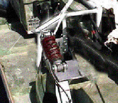
Below are some pictures of the ideas we had for the alignment and suspension. The two figures directly below show what changes we proposed to the chassis and the control arm. To minimize the moment created from the misalignment of the shock and the vertical force from the tires we wanted to align the shock with the force. This alignment was originally part of the first design but due to time constraints the chassis had to be modified in order to keep it from scrubbing the body also. Figure 1 shows the current set-up and Figure 2 shows the proposed changes.
Figure 1 Figure 2
The following figures show the concept versions of the torque mechanism (Figure 3) and the alignment mechanism (Figure 4). The torque mechanism is to be mounted along the chassis and is used to transmit torque from a hand operated crank to gear on the right control arm. A more complete diagram is shown on this page. The alignment mechanism works simply by using apposing threads to add length to different points on the control arm to adjust the alignment of the rear wheels.
Figure 3 Figure 4
![]()