The shear force on the pins will depend on the angle
of the disk and the Force from the maximum allowable
torque of the shaft. An angle of 45 degrees is a
good approximation
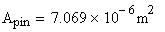
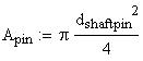
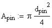
The diameter of these pins must be given to determine
the cross sectional area and the resulting shear stresses
in the pins.
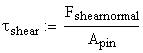
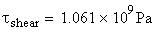
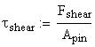
Therefore the shear stress on the pin is:
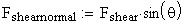
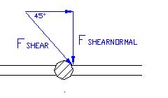
This force is acting at an angle to the pin. If we take
the
component of this force that is acting normal to the
pin, the
maximum shear force can be calculated.
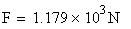
The Force located at this point on the
shaft can be calculated using the equation:
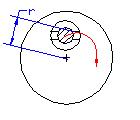
We can picture that on the onset of the seizure the
small pin
will remain stationary with the disk and the shaft pin
will
try to keep rotating. (Hopefully this will not be the
case, but to
determine the maximum shear force, we will assume this).
Therefore, given the distance from the center of the
fuel drive
shaft to the point of contact between the disk pin and
the shaft
pin, the maximum force acting on the pin can be determined:
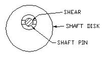
This analysis will take into account the forces acting
on the pin that holds the shaft disk to the shaft pin.
the intent is to determine whether the forces encountered
during a seizure will shear the small pin. Again we
assume the maximum torque to be:
4.0 Shear Stress Analysis- Part 2 (pivoting pin on
disk2 -shaft side)
Therefore it appears that stainless steel would be a
suitable material for the pins
And the Tensile yield Strength is:
For Type 301 cold rolled stainless steel:
In this case, this steel would not be suitable for the
pins
However the Tensile yield Strength is:
For 1040 hot rolled steel The ultimate tensile strength
is :
Depending on the material chosen for the pins, this
design may or may not hold up to the required torque
levels.
6.0 Conclusion
The above calculations will allow the design team to
select a suitable spring which will allow the system
to disengage at the required torque level. The analysis
above has also allowed the team to select materials
for the components which will be suitable for the
operating forces involved in the design.
If we compare this value to the above material strength
values for steel
and stainless steel it is evident that either of the
materials could be used.
However, considering that this is also a very small
component and
the amount of error in our approach and calculation
is unknown,
it may be a wise decision to use stainless steel to
compensate
for any possible error
Therefore the maximum shear stress acting on the pin
is:
The minimum cross sectional area of the shaft pin is
determined from the diameter:
The resulting force at the distance specified is calculated
using the equation:
The maximum torque is obtained from the previous analysis:
In this analysis we will determine if the shaft pin
that is
secured into the shaft will shear at the maximum
torque limit. The shaft pin is located a distance
from
the center of the shaft which is:
Depending on the material chosen for the pins, this
design may or may not hold up to the required torque
levels.
For 1040 hot rolled steel The ultimate tensile strength
is :
However the Tensile yield Strength is:
In this case, this steel would not be suitable for the
pins
For Type 301 cold rolled stainless steel:
And the Tensile yield Strength is:
Therefore it appears that stainless steel can be used
for the pins to withstand the shear
stresses involved.
5.0 Shear Stress Analysis- Part 3 (shaft pin connecting
disk2 to shaft)
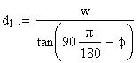
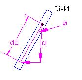
The distance of the force acting on disk one from the
pivoting axis of the disk
is found from the equation:
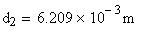
But first the distances d2 and d1 must be calculated
The width of the disks must be specified to find the
distance between the two pivoting axes of the disks.
Again from our final design geometry we have:
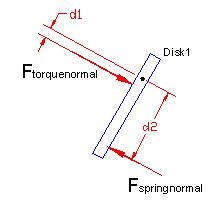
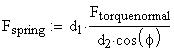
By analyzing the moment about the pivoting
axis of disk 1 we can solve for this spring force:

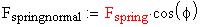
During normal operation this normal force is balanced
by
a force from the spring in a direction that directly
opposes it.
The normal force acting on the
disk from the spring is determined by:
Senior Design Project 2000/2001
Seizure Recovery System for Fuel System Distributor
Final Design Concept Calculations and Analysis
Sponsored
by:
Cummins Engine Company
Team Members:
Michal Brown
Sean Edwards
Keron Miller
Ben Nuttall
Faculty
Advisor:
Dr. Farrukh Alvi
Course
Instructor:
Dr. Cesar Luongo
1.0
Introduction:
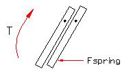
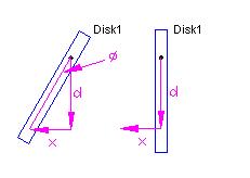
The choice for our final design concept which will be
built and tested is concept #4. The basic operating
principle behind this concept involves two small disks
which are able to pivot. The two disks are placed
so that one surface of each disk is in contact with
the other. A spring applies pressure to one end of
a disk a distance away from the pivoting point. While
at an angle the disks allow torque to be transmitted
during the case of normal operation. In an overloaded
condition, the design of the system allows the spring
to be compressed and the disk become perpendicular
to the axis of rotation of the shaft. While in this
position the shaft is able to spin while the downstream
components are seized.
It is desired to calculate some of the forces involved
in the design and to choose a suitable spring which
will allow the system to disengage at the desired torque
level. It is also necessary to perform stress analyses
to determine suitable materials for the components.
The following calculations will allow the design team
to accomplish this.
For the geometry of the current design please refer
to the manufacturing drawings. They can be found on
the project web page at www.eng.fsu.edu/~nuttall/cummins
(page will be later moved to http://www.eng.fsu.edu/~luongo/design/current.ht
ml)
2.0 Spring Force Analysis
The desired disengagement torque limit specified by
Cummins is given as:
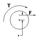
A tangential force will result on the end of the shaft
which will depend on the radial distance between this
point
and the axis of rotation of the drive shaft
For a given radius:
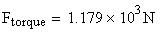
The Force located at this point on the
shaft can be calculated using the equation:
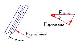
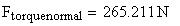
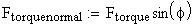
The geometry of the design will place a normal force
on the second disk as a result of the force from the
torque. Based on the angle of the disk this component
of the force can be found. The reaction force from
the second disc is equal to this force when the system
is in equilibrium.
From the geometry of our final design, a maximum angle
of the disk is determined and used in the force analysis.
The shear force on the pins will depend on the angle
of the disk and the Force from the maximum allowable
torque of the shaft:
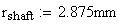
The diameter of these pins must be given to determine
the cross sectional area and the resulting shear stresses
in the pins. From the final design geometry of the
concept we have:
Analysis of this concept must also take into account
the shear forces acting on the pins that hold the disks
in place. If these forces are too great within the
operating torque limits, then the pins will shear before
the torque limiter even begins to compensate for any
overloaded condition.
3.0 Shear Stress Analysis - Part 1 (pivoting pin on
disk1)
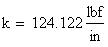
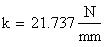
And the spring constant
is:
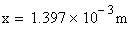
The distance from the point of contact of the spring
to the pivoting axis of disk 1 must also be specified.
However this distance will change as the disk is tilted.
Using the distance between these two points when the
disk is in a vertical position, this length can be
calculated for any angle:
In equilibrium the Moment equation is equal to 0, therefore
we can solve for the spring force.
The spring constant can then be found by
specifying the length that the spring must travel:
Therefore the required spring force to keep the disk
at an angle during normal operation is: