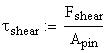
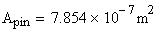
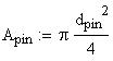
The diameter of these pins must be given to determine
the cross sectional area and the resulting shear stresses
in the pins.
Analysis of this concept must also take into account
the shear forces acting on the pins that hold the disks
in place. If these forces are too great within the
operating torque limits, then the pins will shear before
the torque limiter even begins to compensate for any
overloaded condition.
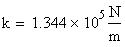
And the spring constant
is:
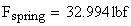
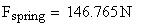
Therefore the required spring force to keep the disk
at an angle during normal operation is:
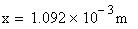
The spring constant can then be found by
specifying the length that the spring must travel:
In equilibrium the Moment equation is equal to 0, therefore
we can solve for the spring force.
Therefore it appears that a material may be chosen for
the pins to withstand the shear
stresses involved.
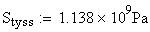
And the Tensile yield Strength is:
For Type 301 cold rolled stainless steel:
In this case, this steel would not be suitable for the
pins
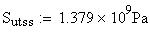
However the Tensile yield Strength is:
For 1040 hot rolled steel The ultimate tensile strength
is :
Depending on the material chosen for the pins, this
design may or may not hold up to the required torque
levels.
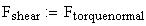
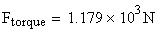
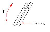
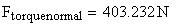
The shear force on the pins will depend on the angle
of the disk and the Force from the maximum allowable
torque of the shaft:
Given an angle of the disk with respect to the axis
perpendicular to the axis of rotation of the shaft:
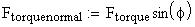
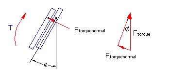
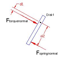
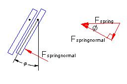
The geometry of the design will place a normal force
on the second disk as a result of the force from the
torque. Based on the angle of the disk this component
of the force can be found. The reaction force from
the second disc is equal to this force when the system
is in equilibrium.
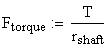
The Force located at this point on the
shaft can be calculated using the equation:
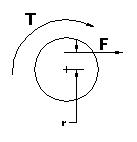
A tangential force will result on the end of the shaft
dependant on the radius of the point in question
For a given radius:
With a given torque limit:
Seizure Recovery System for Fuel System Distributor
Concept #4
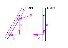
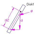
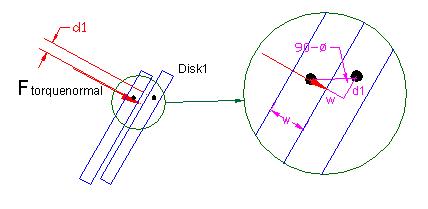
The distance from the point of contact of the spring
to the pivoting axis of disk 1 must also be specified.
However this distance will change as the disk is tilted.
Using the distance between these two points when the
disk is in a vertical position, this length can be
calculated for any angle:
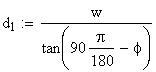
The distance of the force acting on disk one from the
pivoting axis of the disk
is found from the equation:
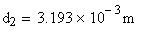
But first the distances d2 and d1 must be calculated
The width of the disks must be specified to find the
distance between the two pivoting axes of the disks
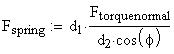
By analyzing the moment about the pivoting
axis of disk 1 we can solve for this spring force:

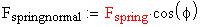
During normal operation this normal force is balanced
by
a force from the spring in a direction that directly
opposes it.
The normal force acting on the
disk from the spring is determined by: