For 1040 hot rolled steel The ultimate tensile strength
is :
However the Tensile yield Strength is:
In this case, this steel would not be suitable for the
pins
For Type 301 cold rolled stainless steel:
And the Tensile yield Strength is:
Therefore it appears that stainless steel can be used
for the pins to withstand the shear
stresses involved.
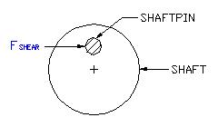
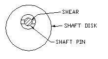
In this analysis we will determine if the shaft pin
that is
secured into the shaft will shear at the maximum
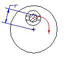
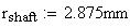
torque limit. The shaft pin is located a distance
from
the center of the shaft which is:
The maximum torque is obtained from the previous analysis:
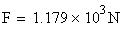
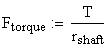
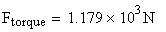
The resulting force at the distance specified is calculated
using the equation:
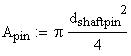
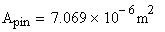
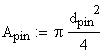
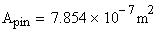
The minimum cross sectional area of the shaft pin is
determined from the diameter:
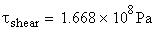
Therefore the maximum shear stress acting on the pin
is:
If we compare this value to the above material strength
values for steel
and stainless steel it is evident that either of the
materials could be used.
However, considering that this is also a very small
component and
the amount of error in our approach and calculation
is unknown,
it may be a wise decision to use stainless steel to
compensate
for any possible error
Seizure Recovery System for Fuel System Distributor
Concept #4
More Shear Stress Analysis
This analysis will take into account the forces acting
on the pin that holds the shaft disk to the shaft pin.
the intent is to determine whether the forces encountered
during a seizure will shear the small pin. Again we
assume the maximum torque to be:
We can picture that on the onset of the seizure the
small pin
will remain stationary with the disk and the shaft pin
will
try to keep rotating. (Hopefully this will not be the
case, but to
determine the maximum shear force, we will assume this).
Therefore, given the distance from the center of the
fuel drive
shaft to the point of contact between the disk pin and
the shaft
pin, the maximum force acting on the pin can be determined:
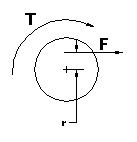
The Force located at this point on the
shaft can be calculated using the equation:
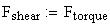
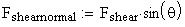
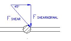
This force is acting at an angle to the pin. If we take
the
component of this force that is acting normal to the
pin, the
maximum shear force can be calculated.
Therefore the shear stress on the pin is:
The diameter of these pins must be given to determine
the cross sectional area and the resulting shear stresses
in the pins.
The shear force on the pins will depend on the angle
of the disk and the Force from the maximum allowable
torque of the shaft. An angle of 45 degrees is a
good approximation
Depending on the material chosen for the pins, this
design may or may not hold up to the required torque
levels.