Our instructor, Dr. Luongo, required several deliverables, the most important are as follows
Our customer, Dr. Harrison, required three deliverables upon completion of this project.
1. A Step-By-Step Process
Dr. Harrison wanted the team to develop a step-by-step process explaining how to create a 3D model of the new solar car body from two longitudinal profiles. In previous years, the solar car's profile was nearly constant across the width of the car (i.e. if the current solar car was cut longitudinally at any distance from the edge, the profile would be approximately the same). The new solar car's profile changes drastically across the width of the car (i.e. if the new solar car was cut longitudinally at any distance from the edge, the profile would be different).The purpose of generating a more complex shape was to incorporate the canopy (i.e. where the driver's head and shoulders are located) more smoothly into the shape of the car to reduce drag.
- Operations Manual
- To view: left-click
- To download: right-click and select 'Save Target As'
2. Computer and Scale Models:
Dr. Harrison wanted the team to demonstrate that the process developed is valid by making a computer model and a scale model to show that the computer's representation of the model is accurate and will translate easily to the real world. The contour of the new body is based on a longitudinal analysis of airfoil data performed by students enrolled in the solar car class during previous semesters. The team was given two longitudes to use as tools to generate the three-dimensional computer model. From this model, latitudes, which are the lateral sections that comprise the contour of the body, and longitudes, which are the lengthwise sections that comprise the contour of the body, were determined from this three-dimensional model. These cross sections are necessary to fabricate the car's design plug, which is a wooden framework that defines the body's general shape. This plug is filled with modeling foam, carefully shaped by hand and then coated with diluted spackling and paint. This coated plug serves as a the male mold during a vacuum bag lamination process. The male mold is coated again with fiberglass and vacuumed until it is hardened. The fiberglass coating is carefully cut into a top and a bottom section and removed from the male mold. These two pieces become a two-piece female mold. Nomex, a honeycomb-shaped strengthener is then laid into each piece of the female mold, coated with XXX3 and allowed to harden. The combination the hexagonal strengthener and the XXX3 yields a new body.
3. Preliminary chassis design
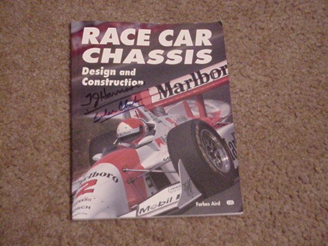
Dr. Harrison required the team to design a chassis to fit inside of the new body. The chassis is the framework to which components such as the suspension, driver's seat, dashboard, and body are attached. In the event of a crash or collision, the chassis absorbs much of the impact forces and distributes them. In order to understand the principles behind chassis design, Dr. Harrison lent the team a book entitled Race Car Chassis Design and Construction by Forbes Aird. The basic idea behind chassis design is triangulation of three-dimensional cubes to distribute forces