Project Scope:
The main part of this project involves developing a process to generate a three-dimensional model for the new solar car body. The planned shape is based on a longitudinal analysis of airfoil data performed by students enrolled in the solar car class during previous semesters. Latitudes (cross-sectional slices), which are necessary to fabricate the body of the new solar car, will be determined from this three-dimensional model.
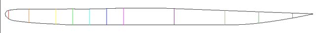
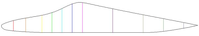
The team was given two cross-sections to work with. One is a profile of side edge of the car and the other is of the centerline (what you would see if the car were cut vertically in the lenghtwise direction) of the model's body. We must use solid modeling software (such as Pro/Engineer or Mechanical Desktop) to generate surfaces from these cross-sections, which will involve importing either AutoCAD drawings or sets of data points from Microsoft Excel into the solid modeling software. The curvature of the surface of the car must be relatively gentle to accommodate stiff laminated solar cells. Ideally, the lift and drag on the car should be zero. However, such parameters are nearly impossible to accomplish or calculate based on a computer model because of the computing power such calculations necessitate. The team was also given competition regulations to use as guidelines as specified by Formula Sun, who governs the Formula Sun Grand Prix, which is the race that the FAMU-FSU CoE competes in during the month of May each year. The customer would like to have the appropriate cross-sections finished by the end of the 2001 fall semester 2001.
Provided that the three-dimensional model and corresponding latitudes are completed
during the fall of 2001, preliminary chassis design work and scale model construction
will begin during the 2002 spring semester. Before the team physically builds
this model, it should generate a new 3D model of the solar car body based on
the AutoCAD drawings in the Final Fall Design Package to create a more accurate
3D model. In other words the team will try to blend longitudinally (in the direction
of the length of the car). This could be done in one of two ways. The first
method involves using Pro/E to create a new set of Pro/E section files to use
as the sections of a blend. These new sections would be created based on the
seventeen AutoCAD engineering drawings. The other method involves using Mechanical
Desktop (MDT), which is based on AutoCAD, to create a loft, which is the MDT
equivalent of a blend. The team will explore the potential of the use of Mechanical
Desktop (MDT) to create a new 3D model of the solar car. This new model will
include radii along the edges of the car's body and improved curvature over
the canopy and front spine.
The team anticipates fabricating several iterations of the physical model. Dr. Harrison wants to create a physical scale model to check the curvature of the car, which must be gentle enough to allow the photovoltaics to be properly fastened to the car's body. He feels that this curvature can be deceiving when viewing a CAD model. Once a suitable new 3D model is created in Pro/E or MDT, the latitudes used to create it will be used to create scaled down wooden model latitudes to be used in creating the plug of the scale model car. This plug will then be filled with high-density foam, shaped, coated and evaluated. If the shape needs to be refined further, another scale model will be made, using modified latitudes.
Once Dr. Harrison is satisfied with the curvature of the car, design work will
begin on the chassis of the car. This involves, making sure that a new chassis
fits inside the body of the new car, considering how the canopy will be cut
out from the body, where the wheel wells will be located, and possible chassis
attachment locations. There are AutoCAD drawings of the current chassis on which
new designs will be based.