Pictures
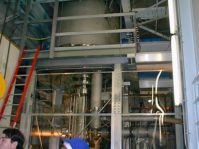
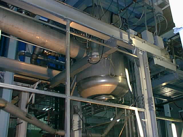
These two pictures are of the hybrid magnet. The left picture is the base of the hybrid magnet, which is three stories tall. The rigth picture shows the evaporator vessel for the helium.
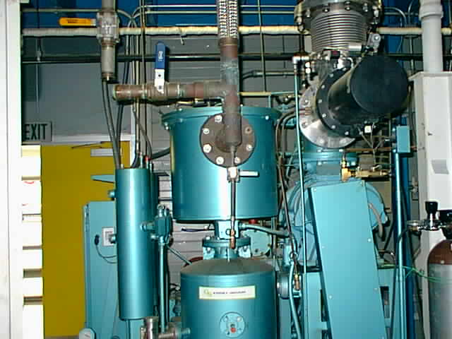
These two pictures are of the vacuum pump. The right picture shows the seals that have swollen over time.
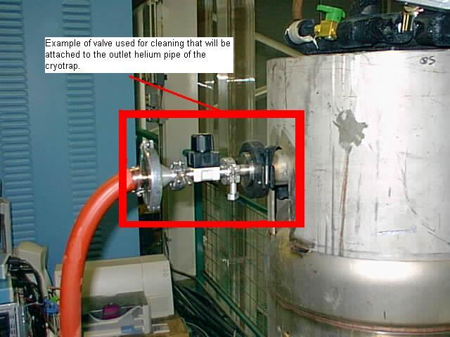
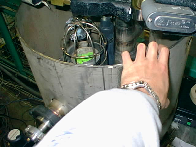
Here the team is taking a look at an existing cryotrap. The left picture shows how a vacuum valve is attached to the cryotrap, and the other picture shows the inside of the cryotrap.
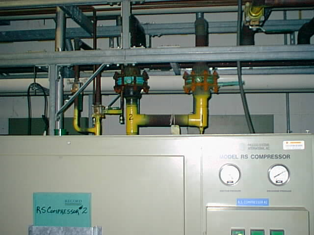
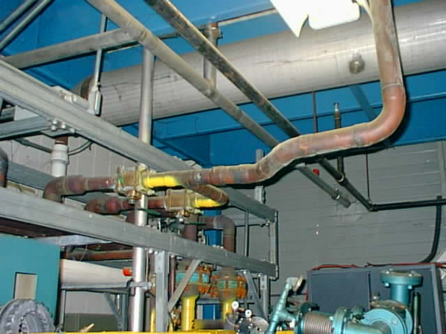
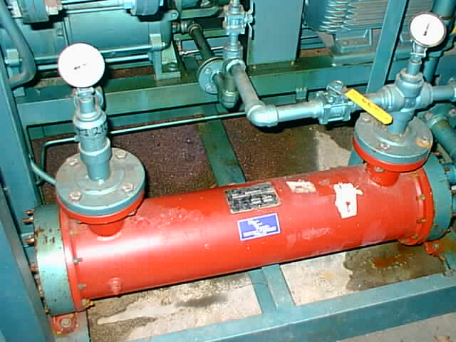
The picture on the left shows the compressor. The one on the right is the current piping layout above the compressor, which the cryotrap must fit into.
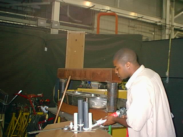
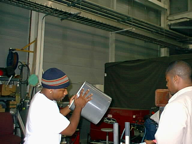
Here Gerard diligently works, trying to put the model together. Here Bryan assists Gerard in putting the Liquid Nitrogen Tank together.
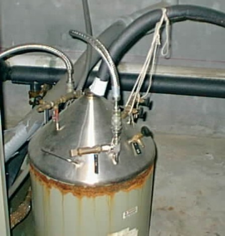
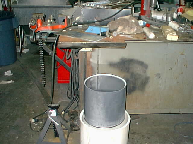 These are the liquid nitrogen vessel and vacuum jacket unassembled.
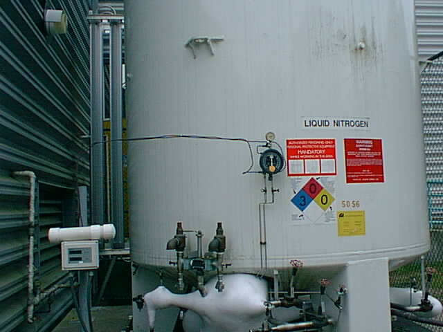
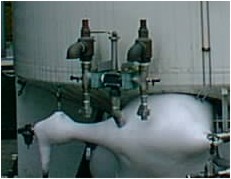
The liquid nitrogen tank for the NHMFL, with an extreme close-up of the ice that has formed around the piping.
 A
picture of the old cryotrap for the Hybrid Magnet.
A
picture of the old cryotrap for the Hybrid Magnet.
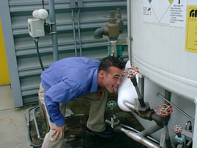
Eric gets a taste for the project early on.
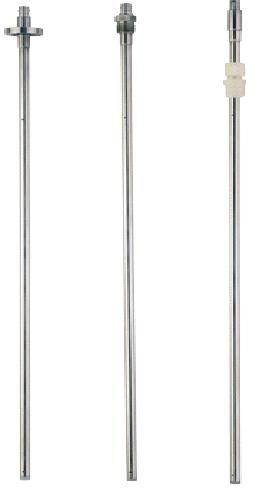
These pictures represent the monitoring system and thermocouple of the liquid level monitor for the nitrogen control system.
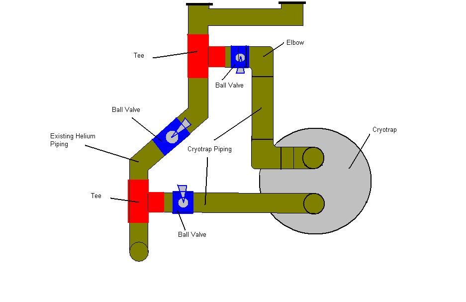
This is a hand drawn picture of how the cryotrap should be placed within the existing piping. The red are tee splits, the blue ball valves, the green is piping, and the oval is out cryotrap.