- On the other end of the stem is screw thread.
This will be screwed into the hole in the pendulum ball.
This should be screwed in as tightly as possible.
- The assembly should now look like Figure 3-5 below.
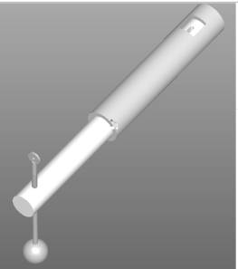
Figure 2-6:
Partial Assembly to Step 13
- Pin hole 2 will be attached with the same procedure as
the pendulum shaft pin hole.
- This stem will then screw into the hole on the top of
the large diameter shaft. It
should be screwed in as tightly as possible.
- It is also important to make sure that it is not
turned once it is set. This
could cause errors in data.
- The face of pin hole 2 should be parallel with the
face of pin hole 1