|
Volume 1 |


Famu-fsu
College of Engineering
Inclinometer testing procedures
&
Prototype Assembly/ Testing Guide
|
Volume 1 |
Famu-fsu
College of Engineering
Inclinometer testing procedures
&
Prototype Assembly/ Testing Guide
Famu-fsu College of engineering
Inclinometer
Testing Procedures & Prototype Assembly/Testing Guide
ã FAMU-FSU College of Engineering
2525 Pottsdamer Street • Mechanical Engineering Department
Phone 850.410.6335 • Fax 850.410.6337


Table of Contents
Inclinometer Testing
1.1.3 DYNAM
Program and Mechanical Pendulum
1.3.1.2 Magnetic
Field Testing
1.3.2.2 Magnetic
Field Testing
Prototype
2.3 Experimental Setup and
Procedure
APPENDIX
3.0 Appendix
1: Prototype Parts
|
Section 1.1 Experimental Apparatus |
Inclinometer Testing
Figure 1‑1:
Test Mount Assembly Bottom Plate Top Plate Mounting Platform Spring Nylon Tubing![]()
![]()
![]()
![]()
![]()
![]()
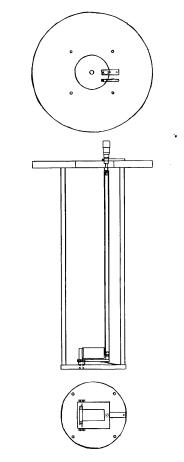
Figure 1-1 displays the test mount, which was constructed using aluminum 6061. The test mount works on the geometric principle of relating distance to angle measurements. The micrometer, which is mounted to the top of the device, is connected to a nylon tube. This nylon tube is connected to the mounting plate, which is supported by a spring. The inclination angles are regulated using the micrometer. Changing the reading on the micrometer changes the angle of the mounting plate. Table 1-1 displays the relationship between the micrometer reading and the plate inclination angle.
Table 1‑1: Micrometer Reading - Inclination Angle Relationship
|
Degree |
Micrometer
Reading |
|
3.0° |
2.81 |
|
2.5° |
2.67 |
|
2.0° |
2.54 |
|
1.5° |
2.40 |
|
1.0° |
2.27 |
|
0.5° |
2.13 |
|
0.0° |
2.00 |
|
-0.5° |
1.87 |
|
-1.0° |
1.73 |
|
-1.5° |
1.60 |
|
-2.0° |
1.47 |
|
-2.5° |
1.34 |
|
-3.0° |
1.21 |
On the top of the test mount, a probe head containing a Deuteronics 19-pin connector is mounted opposite of the micrometer. This 19-pin connector connects the mounting 6-pin male connector, which connects to the female pin connector of the inclinometer, to the breakout box.
|
Section 1.1 Experimental Apparatus |
The Crossbow CXTA01 accelerometer is a single and dual axis analog tilt sensor, which has a design based on a silicon micro-machined capacitive inclination sensor element. The CXRA01 tilt sensor has a DC response to measure inclination relative to gravity. The CXTA01 has a 5-pin connection (see Figure 1-2). The pin numbers and functions can be seen in Table 1-2 below.
Table 1‑2: Accelerometer Pin Connection Reference Table
|
Pin |
Color |
Function |
|
1 |
Red |
Power |
|
2 |
Black |
Ground |
|
3 |
White |
Pitch |
|
4 |
Yellow |
Roll |
|
5 |
Green |
Temperature |
The DYNAM software was developed for calculating and displaying static and dynamic inclinations and profiles using Microsoft Windows. The DYNAM software is part of the components of the digitized ZEROTRONIC family developed by WYLER AG, which offers higher accuracy. The system is fully digitized and allows the transmission of signals over long distances without loss of accuracy. All the sensors and instruments of the ZEROTRONIC family can be operated with the DYNAM software.
The pendulum itself is a ZEROTRONIC sensor, whose measuring principle is based on the changing of the capacity of a capacitor and the pendulum. The measured change in capacity is directly influenced by the change of the inclination of the pendulum. The capacity change is the signal that is primarily used for the angle to be measured.
|
Section 1.1 Experimental Apparatus |
The multi-meter used was the TENMA True RMS Digital Multi-meter 72-410A has an accuracy of 0.001V. The maximum power through the device is 10W.
The breakout box was designed and constructed by the staff at the National High Magnetic Field Laboratory. It has 18-pin connections and a ground, which correspond to the Deuteronics 19-pin connector.
The power supply used was a Harrison 6253A Dual DC Power Supply. It has a voltage range of 0-20V and an amperage range of 0-3A.
The program used to control the magnet was LabView 6i: PS Control. This program allows the magnetic field produced by the magnet to be controlled by the user.
|
Section 1.2 Experimental Setup |

Figure 1-3: Accelerometer Orientation on Mounting Plate
![]() Warning!!
All data collection materials must be beyond the 10 Gauss line.
Warning!!
All data collection materials must be beyond the 10 Gauss line.
![]() Warning!!
Be sure to connect sensor and power supply to the corresponding ports.
Warning!!
Be sure to connect sensor and power supply to the corresponding ports.
![]() Warning!!
All data collection materials must be beyond the 10 Gauss line.
Warning!!
All data collection materials must be beyond the 10 Gauss line.
|
Section 1.3 Experimental Procedure |
![]() Warning!!
Do NOT adjust micrometer reading in magnetic field greater than 0T.
Warning!!
Do NOT adjust micrometer reading in magnetic field greater than 0T.
![]() Warning!!
Remove all credit cards, cellular phones, jewelry, etc. before testing: these
items may be damaged in magnetic field.
Warning!!
Remove all credit cards, cellular phones, jewelry, etc. before testing: these
items may be damaged in magnetic field.
|
Section 1.3 Experimental Procedure |
![]() Warning!!
Do NOT adjust micrometer reading in magnetic field greater than 0T.
Warning!!
Do NOT adjust micrometer reading in magnetic field greater than 0T.
![]() Warning!!
Remove all credit cards, cellular phones, jewelry, etc. before testing: these
items may be damaged in magnetic field
Warning!!
Remove all credit cards, cellular phones, jewelry, etc. before testing: these
items may be damaged in magnetic field
|
Section 2.1 Prototype Assembly |
Prototype
Parts Needed: Solid shaft, larger diameter hollow shaft, 2 identical pin holes, 2 identical deep groove ball bearings, 2 long stems, 1 short stem, 2 mirrors, pendulum ball, Hollow cylindrical shell
These are detailed instructions to assemble the prototype from its parts.
Hole 1 Shaft 1 Hole 2
![]()
![]()
![]()
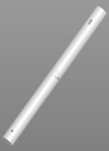
Figure 2‑1: Shaft 1
|
Section 2.1 Prototype Assembly |
Hole 3 Shaft 2 Slot 1
![]()
![]()
![]()
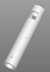
Figure 2‑2: Shaft 2

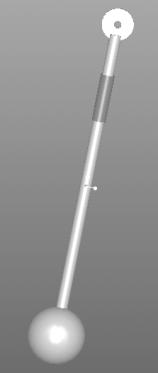
Figure 2‑3: Completed Pendulum Stem
|
Section 2.1 Prototype Assembly |
Rectangular Stem

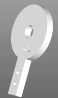

Figure 2‑4: a.) Pin Hole; b.) Exploded View of Pin Hole Assembly
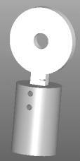
Figure 2‑5: Completed Pin Hole Assembly
|
Section 2.1 Prototype Assembly |
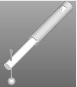
Figure 2‑6: Partial Assembly to Step 13
|
Section 2.1 Prototype Assembly |
Mirror Stem Pin Hole 2
![]()
![]()
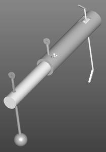
Figure 2‑7: Completed Assembly without Outer Casing
Outer Casing![]()
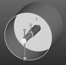
Figure 2‑8: Finished Assembly
|
Section 2.1 Prototype Assembly |
|
Section 2.2 Experimental Apparatus |
The Metrologic Laser-Power meter was used to measure laser intensity. This is the major factor in the precision of the readings. This device has a range of 20 microwatts to 20 mW. This device may also be replaced in experiment. If it is replaced by a power meter that allows smaller readings, more precise readings may be taken.
Laser diode control unit by Power Technology, Inc. This was model: LDCU3/3663. This type of laser is Neodymium Ytrrium Argon Garnett (Nd:Yag).
The laser has and output power of 10 mW and a wavelength of 532nm. This laser has a beam diameter of 1mm with a tolerance of .2 mm. The laser may be changed as long as the beam diameter is 1 mm or larger.
![]() Warning!!
Do NOT stare directly into the laser beam emitter. Will cause blindness.
Warning!!
Do NOT stare directly into the laser beam emitter. Will cause blindness.
Figure 2-8 is the completed device. It will be used to change the intensity of the light that goes in. The angle of tilt of the device is a function of the intensity that comes out of the device. The detector used to measure the intensity of light for this product must have a higher sensitivity than that of the detector used in the proof of principle prototype assembly experiment. The recommended detector for use with this product is the New Focus 2151 Femtowatt Photoreceiver, which has a detector diameter is 1.0mm. This detector measures wavelengths in the range of 300-1050nm with a maximum responsivity of 0.5 A/W.
|
Section 2.3 Experimental Setup |
Once the assembly is completed, the prototype is ready to set up. All testing surfaces used should be at zero degrees in reference to the horizontal plane. It should always be perpendicular to gravity.
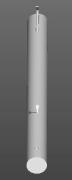
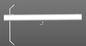
Figure 3‑3‑1: Front and Side View of Axial Cylinder with Mirror Mounts Attached
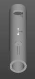
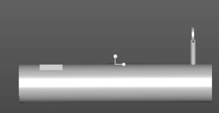
Figure 3‑2: Middle Shaft with Pin Hole Attachment

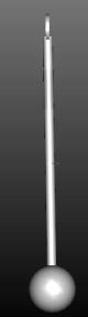
Figure 3‑3: Pendulum Shaft with Set Screw and Pin Hole Attached

Figure 3‑4: Base Cylinder of Prototype
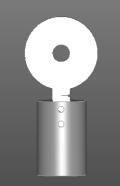
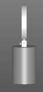
Figure 3‑5: Pin Hole Attachment