Group
13: Aquaculture Kit
Operation
Manual
Ben
Ellis
Brian
Hammond
Pamela
Mills

Group
13: Aquaculture Kit
Operation
Manual
Ben
Ellis
Brian
Hammond
Pamela
Mills
Congratulations on the purchase of your Group 13 solar water heating
system! Every component in this system has been engineered or selected for its
performance, reliability, and cost-effectiveness. Each kit is specially tailored
to the needs of each customer. No two systems are the same. The kit’s most
valuable component is our expertise and support!
This manual will familiarize you with the installation, operation and
maintenance of the solar system. All applicable building, plumbing and
electrical codes regarding solar water heating systems are to be followed. While
the performance of solar system can be estimated for a certain area, there is no
given number because of the different factors involved. Factors that affect
system performance are: the amount of solar radiation at a site, local weather
conditions, ambient air temperature, average ground water temperature, tilt and
azimuth angle of the solar collectors, shadowing from nearby objects, solar
system sizing and hot water demand.
This system is partially assembled by Group 13 prior to shipment.
However, some aspects of the system are not cost effective to build and ship,
and must be constructed on site. These include the solar collector frame, the
system slab, and the greenhouse. The greenhouse and slab considerations are left
to the discretion of the end user. The solar collector frame may be constructed
in several ways, and must meet local building codes. Plans for frames suitable
for Florida and Georgia are available from Group 13 at no additional cost.
WARNING:
Specifications may change without notice. Intended for
licensed factory authorized installers only! Users should review separate owners
operational manual.
NOTE: Failure to properly winterize the unit will void the
unit warranty.
Please ensure that this manual is read in its entirety prior to
commencement of installation. Failure to comply with instructions listed in this
manual can cause product/property damage, severe personal injury, and/or loss of
life.
| A
licensed professional heating contractor must perform all installation,
service and maintenance of the solar system. | |
| A
licensed professional gas technician must perform all installation, service
and maintenance of equipment involving gas connections. | |
| A
licensed professional electrician must perform all installation, service and
maintenance of equipment involving high voltages. | |
| Do
not spray cold water on the surface of a hot solar collector that has been
sitting idle outside in the sun for some time. | |
| Do
not touch any plumbing with your bare hands when the solar system is
operating as the temperatures can burn instantly. |
All information contained in this manual is believed to be reliable and
accurate at the time of writing. However, the manufacturer is not responsible
for any errors, omissions or damages resulting from the use of this information.
CAUTION: IF
YOU DECIDE TO WASH THE UNIT WITH A HOSE, DISCONNECT ALL POWER TO
THE EQUIPMENT PAD, INCLUDING THE POOL OR SPA EQUIPMENT TO PREVENT POSSIBLE
ELECTRIC SHOCK.
This system is intended as an
addition to an existing aquaculture system, and can also be built with a new
aquaculture system. As such, certain components mentioned in the kit are not
actually included with the kit. These include the existing aquaculture tank,
pumps and filtration systems. The heat storage tank is also expected to be
furnished by the end user, as each different system will require different sizes
and styles of tank. Of course, Group 13 will be happy to help recommend tank
specifications and will also assist in locating appropriate plans or tanks.
| Heat
Collector Pump: a pump sized
to the needs of your system is included. Appropriate pump start relays and
manual override switches are boxed up with the pump. A certified electrical
contractor should closely follow these instructions. Do not replace with a
larger or smaller pump as system reliability or effectiveness may suffer. | |
| Solar
Collectors: FifCo 48” by
144” collectors are supplied in the number needed for each application.
These can be plumbed in parallel to increase capacity to any amount needed.
The angle of inclination required is included in the spec sheet packaged
with the collector. | |
| Heat
Exchanger: A heat exchanger
is selected and supplied for each kit that will best meet the needs of the
customer. | |
| Control
Box: A controller for each
system is assembled and calibrated at the factory. All necessary wiring and
sensors are included. Detailed wiring diagrams are included in the
controller packaging. A certified electrical contractor should closely
follow these instructions. | |
| Control
Valves: Appropriate valves
for directing water flow are also supplied in the kit. Individual
manufacturers include detailed operation and wiring instructions with the
valves. Valves included are generally low cost irrigation style valves. They
are easily and inexpensively serviced in the case of a failure. |
It is recommended that qualified personnel perform the installation of the kit.
It is most efficient to place the
components near to one another. This shortens pipe runs and minimizes losses to
the atmosphere. Placing the heat exchanger between the storage and aquaculture
tank simplifies valve bypass plumbing. Allow a prudent amount of space on all
sides of each component to facilitate servicing in the future. The solar
collector should face due south.
The
plumbing details are site specific, and must be planned for each individual
installation. However, the overall routing is the same for each system. If help
is needed in plumbing design, simply call Group 13 for assistance. The following
are some plumbing guidelines:
| The
solar collector should be as close as possible to the heat storage tank to
minimize energy losses by shortening pipes. Of course, the solar collector
should not be in the shadow of the greenhouse. | |
| Plastic
to plastic NPT fittings should be sealed with Teflon tape. | |
| Plastic
to metal NPT fittings and metal-to-metal NPT fittings should use a liquid
thread sealer. | |
| Shutoff,
bypass, and drainage valves should be placed throughout the system in
strategic positions. Any component of the system should be able to be
bypassed and serviced without disrupting the aquaculture tank operation. | |
| PVC
fittings should be cleaned with an acetone-based primer prior to gluing. PVC
pipes should be insulated with readily available hardware store sch40 iron
pipe insulation. |
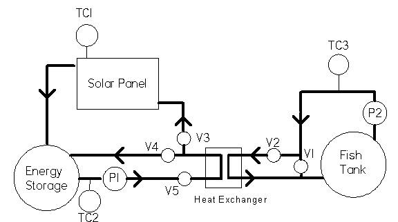
The heat exchanger
uses NPT fittings and can be attached to the plumbing using standard male and
female adaptors. The heat exchanger should be plumbed to promote a cross flow
situation. Valves are cast with markings indication fluid flow and also accept
PVC NPT adaptors. Review the following plan for plumbing schematic details:

The heat storage system pump uses a high
voltage and amperage power source. Follow all applicable building codes while
installing any electric device. The pump should be equipped with the included
throttling valve just downstream of the discharge. The throttling valve is
pre-set and marked to provide the required fluid flow rate.

The
solar collector frame construction is not covered in this manual. The solar
panel should be attached to the frame using the supplied hardware. The collector
should be framed with 1”x4” around the edges perpendicular to the collector
and raised 2.5” above the frame platform. This will serve as a mounting point
for the heavy clear plastic cover. Plexiglas may be substituted, but is not
recommended, as it is costly. The solar collector cover minimizes conductive and
convective losses by providing an insulating air buffer. This effect is lessened
if the cover is in contact with the solar collector.
Once all of the components are
installed and wired, the following procedure should be performed:
1)
Fill heat storage tank with water. If in a climate that requires winter
freeze protection, add water softener salt in the amount needed. (1 lb/gallon to
20°F, 2 lb/gallon to 10°F, and 3 lb/gallon to 0°F; 3 lb/gallon is a saturated
brine mixture)
2)
Open all solenoid valves by loosening bleed screws.
3)
Open all bypass ball valves and throttling valve.
4)
Manually turn on aquaculture and heat storage pumps.
5)
Allow system to run until all air bubbles are flushed out of system.
6)
Begin closing bypass valves one at a time until they are all in their
standard service positions.
7)
Carefully check system for leaks. If any are found, repair them now.
8)
Partially close throttling valve V5 to its marked position to set solar
panel flow rate.
9)
Begin closing solenoid bleed screws to shut off valves V2 and V4. This
will put system in heat collection mode. Run in this position while recording
heat storage tank water temperature. You should observe a temperature increase
of approximately 1-3°C per hour in ideal conditions. This process will take
several hours, and may take more than one day in poor conditions. The system
should be shut down at night.
10)
Once the system has reached operating temperature (about 43°C), open the
bleed screws on valves V1 and V3 and close the bleed screws on valves V2 and V4.
This puts the system in aquaculture heating mode. Record the temperature changes
in the aquaculture tank. You should see a temperature gain of approximately 8°C
per hour.
11)
When the aquaculture tank
has reached its operating temperature, shut off both pumps and close all bleed
screws. Switch Controller box to “automatic.” The system should now be
operating and maintaining temperature of its own accord.
12)
Observe the system for several days for proper operation, noting tank and
ambient temperature and weather conditions. You are now ready to begin growing
aquaculture!
Use the following steps to find and correct any problems encountered in
start-up:
|
Symptom |
Cause |
Solution |
|
No
Fluid Flow Through Pipes |
Pump
not running |
Check
wiring |
|
|
Valve
not open |
Check
ball valves and solenoid valves for |
|
|
|
Proper
operation and position |
|
Heat
Tank Not Collecting Energy |
Valve
not positioned properly |
Check
schematic and valve position |
|
|
Solenoid
valve not actuating |
Test
for 24 VAC at solenoid |
|
|
Throttling
valve miss-adjusted |
Check
and correct position |
|
|
Ball
valve closed |
Check
ball valve |
|
|
Solar
collector bypassed |
Set
bypass valves to service position |
|
Aquaculture
tank not warming up |
Valve
not positioned properly |
Check
schematic and valve position |
|
|
Solenoid
valve not actuating |
Test
for 24 VAC at solenoid |
|
|
Ball
valve closed |
Check
ball valve |
|
|
Throttling
valve adjusted-adjusted |
Check
and correct position |
|
|
Heat
exchanger bypassed |
Set
bypass valves to service position |
Should
any problems arise that are not solved in the start-up troubleshooting guide,
contact Group 13 technical support for assistance.