This is the Thermo-Fluid System Layout. Click a component for a description.
Fluid Routing for Energy Collection
Fluid Routing for Aquaculture Tank Heating
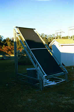
The system will use a pool type solar collector for energy gathering. The
collector chosen is a low cost, low efficiency design manufactured by FAFCO. It
is designated the Revolution 912R, and has an effective collection area of 47.5
square feet. The overall size is approximately 12’ by 4’. The
manufacturer’s recommended flow rates are from 4 to 8 gallons per minute, and
the collector is expected to be most effective at 6 gallons per minute. In
comparative testing done by the Florida Solar Energy Center, this model was one
of the most capable of its design type. This solar collector is modular, and if
it cannot satisfy the needs of the system, an additional panel can be added,
doubling the energy collection capacity.
The low efficiency inherent in this device is not a concern as the overriding design criteria is that the system be inexpensive. Solar energy is free and renewable, offsetting problems with low efficiency.
Aquaculture Tank/ Energy Storage Tank
•Size:
4’ diameter x 3’ deep
•Material:
Polymer (unspecified plastic)
•Insulation:
Styrofoam sheeting (2” thick)
•Circulation
requirements: 5-8gpm heat storage circuit/ 15gpm aquaculture circuit
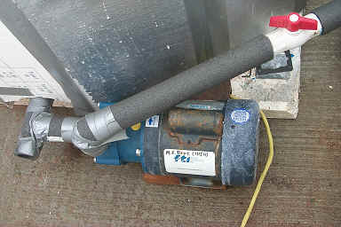
Two pumps will be used for the system, since the heat storage and the
aquaculture tank are separate systems. The heat storage system will use a 1/3 HP
centrifugal pump. This pump exceeds the customer specifications and will supply
a flow rate of 8 gallons per minute. It
will also allow the end user to closely control fluid flow rates with a
throttling valve to achieve optimum solar collector performance.
The aquaculture system will be run with a ½ HP centrifugal pump. This
pump is widely available, inexpensive, and easily serviced across the country.
This pump is also slightly larger than what is necessary, and will allow the end
user to have a wide range of flows in their system. This is important, as
different varieties of marine life require various flow rates in the tank to
promote growth and to operate filtration systems.
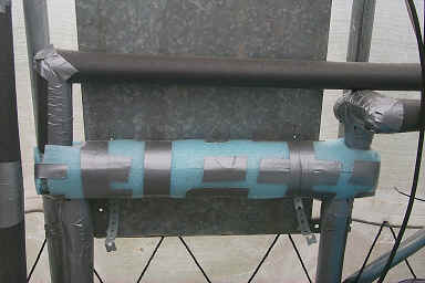
The original design iteration included a high efficiency stacked plate
type heat exchanger made by Lytron. This product most closely satisfied the
design requirements of the project. However, due to budget constraints the
actual heat exchanger to be used is a tube in tube type donated by the Dr. Shih.
This heat exchanger has less desirable geometry, but is 3 times the volume of the originally selected heat exchanger. It has been determined that the heat exchanger design can exchange energy at a rate greater than 4.4 kW notwithstanding massive losses to the surroundings. This heat exchanger is sufficient for this project’s purposes. The picture above shows the insulation covering the heat exchanger.
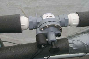
The valves research pertained
to the operation and controllability. Any
type of valve would be sufficient because of the low pressure and moderate flow
through the system had they not needed to be controlled.
Diaphragm-solenoid valves were selected because of the feasibility of
implementation into the controller. The
valve selection was also based on temperature range of the water inside the
pipes, the diameter of the pipe, pressure, and the flow through the pipes.
Both normally open and normally closed valves will be used in the final
design of the system. One draw back
to the valves selected is the short life cycle but this type of valve is easily
and inexpensively repaired making them ideal for use in this system.