

Building Process
The processes described below may be hazardous and should only be attempted by those with machine shop experience.
Steering Arm Construction
Front
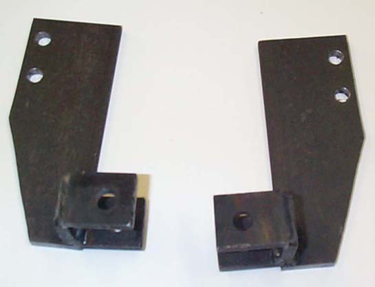
The steering arms are made from two inch wide quarter inch steel flat bar. The first step is to cut the flat bar into the shape of the top surface of the steering arm on the band saw. Then the three pieces that make up the u tab that the tie-rod bolts onto need to be cut the dimension of two of these are 1 inch by 1.25 inches the other one is a 1-inch square. Next drill a 3/8” hole in each of the tabs that are 1” x 1.25” this hole goes a 1/2” in from one end in the center. Then drill the two mounting holes in the main part of the arm to do this use a steering arm that is still in good shape for a template to insure that it will fit on the upright to drill these holes use a N size drill bit. Once this is done then u tab can be welded together and welded to the main part of the steering arm.
 Rear
Rear
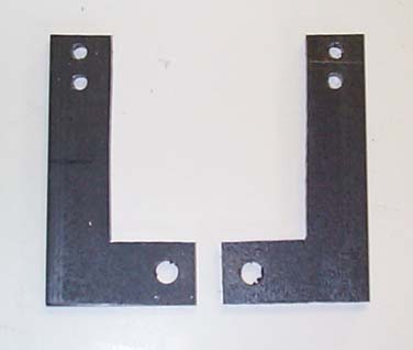
The rear steering arms are made from the same material as the front steering arms. First cut out the shape of the arms then drill the 3/8” hole in the tab section and the two Ľ” holes for mounting in the other end of the arm. Finally put the arm in a vise with the tab section sticking up, using a torch heat up the part were the tab section meets the main section once this is hot use a piece of square tubing that fits over the tab to bend it to a ninety degree angle. Once this is done the steering arms are finished.
Tie Rod Construction
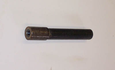
If the end caps are already made make sure that you have one that is left handed thread and one that is right handed thread if not the end caps need to be made. The end caps are made from a piece of ľ” steel round stock. The first thing that needs to be done to make the end caps is to drill a hole in the center of the stock using a Q drill bit, the best way to do this is to use the lathe. Once this is done use the lathe to spin down a section 3/8” long and 0.036” deep. Then this section needs to be cut off the rest of the stock cut the piece so that it is about 9/16” long on the horizontal band saw, and clean them up on the lathe so that the entire piece is only ˝” long. The last thing that needs to be done on the end caps is to thread them using a 3/8” tap this can be done on the lathe as well make sure that half of the end caps a right handed and half are left handed. The next step in making the tie rods is to cut the ľ” 0.036 wall steel tubing to about 5 Ľ” long. Now weld a left handed end cap to one end and a right handed end cap to the other end. The last part that needs to be done is to thread the tie-rod ends into the end caps and install on the car.
Shaft Construction
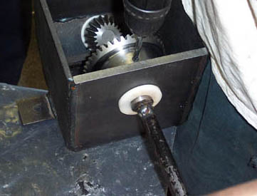
To construct the shafts, measure the distance between the rack and pinion assembly and the gear adapter. Mark the tubing to this length. Using a hacksaw or band-saw you can cut the tubing to the proper length. Place the tubing in the proper position and mark the proper placement of the holes to be drilled. Remove the tubing. Using a drill, carefully drill the holes on the markings. Replace the tubing and fasten to the rack and gear adapter respectively.
If constructing the rear shaft repeat the previous procedure noticing that one end will join with the U-joint and the other with either the rack or gear adapter.
Several components/modifications besides those listed here were made to allow the four-wheel steering system to be installed onto the existing baja car. These parts may be seen under the assembly/manufacturing pictures in the picture gallery. However, these parts are not considered to be a part of the four wheel steering system which we designed, but rather parts of the car's suspension or chassis, which had to be modified to accept the new design.
The processes described below may be hazardous and should only be attempted by those with machine shop experience.
|
Tools Used: Drill Press 3/8” drill bit letter N and Q drill bits 1/4” drill bit 3/8” Tap right and left handed Band saw Horizontal band saw Welder Lathe Torch |
Materials Used: SAE 1018 steel Steel Tubing ľ” diameter (0.036" wall) ľ” steel conduit tubing |
Front
Tie Rod Construction
Shaft Construction