

Design Process
The task presented to this design group in August 2003 was to design a four-wheel steering system for the Florida State University SAE Mini-BAJA car. The purpose of this system is to significantly reduce the turning radius of the vehicle, thereby improving the performance of the vehicle during competition.
Many factors were taken into account when designing this system. The foremost criteria of the design was the reduction of the turning radius to seven feet or less.
Stability of the vehicle during turns was also taken into consideration. The durability of the components was perhaps the most scrutinized factor having by far the largest amount of data for comparison. Among the other factors considered were system weight, proximity to moving components, application to other vehicles and lastly, budget.
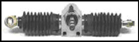
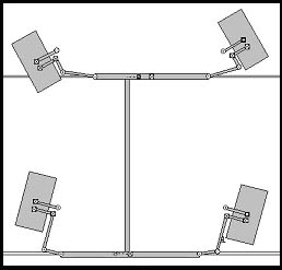
Many of the concepts considered for this system are partially derived from existing systems used on vehicles. The concept chosen for this system implements a 5” travel rack and pinion assembly for both the front and rear subsystems.
The steering column is fitted with a 2” 45 degree bevel gear mated to a 2” bevel gear for the front and a 4” bevel gear for the rear. This provides a maximum rack travel of 5” for the front subsystem and 2.5” for the rear.
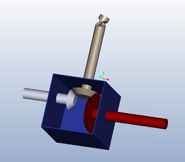
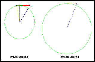
This translates to a maximum wheel angle of 30 degrees in front and 15 degrees in the rear. The rotational force is transferred to the pinions by means of shafts that run from the gear box to the rack and pinion assemblies
The geometry of this system was produced to provide the desired turning radius while maintaining the stability of the vehicle. Concerns were raised about the possible toggling of the front system if the front wheel angle was too large. Research of the front wheel angles of most production cars manufactured today showed that most implement an angle between 28-32 degrees depending on the intended application of the vehicle. Based on this data, along with the toggling concerns, the group felt it wise to define the front wheel angle at 30 degrees. At this time the stability of the car was addressed. Increasing the rear wheel angle could produce a smaller turning radius but may lessen the stability. Research was conducted concerning front to rear wheel angle ratios but no data could be found. After much debate a front to rear ratio of 2:1 was chosen giving a 15 degree rear wheel angle.
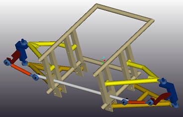
The whole steering system has been modeled in Pro-Engineer for multiple reasons. The first of which is for use in the design of the system, making sure that none of the components interfere with critical components of the car such as the drivetrain. Another for doing the Pro-E modeling is to help with the fabrication of the steering system. The front steering system is shown below.
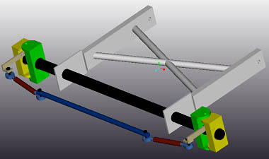
The rear steering subsystem is shown below.
The stability of the vehicle cannot be quantified but will be tested after construction and recorded qualitatively.
This system was designed to withstand the impact of hitting an obstacle at 20 mph with the collision occurring over .55 seconds.
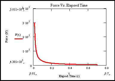
Factoring in the mass of the vehicle with the largest expected driver the collision produced a force of approximately 5600 N. This force is applied directly to the steering linkage without regard to the component of the force which would be absorbed by the suspension. This is obviously a worst case scenario which would not be anticipated even under the most extreme circumstances. In addition to this assumption a factor of safety of 1.5 was designed into the system. Taking into account the compressive/tensile forces along with the bending moments and shear forces it was found that the typical steel used in most steering components, AISI 1018, would be sufficient in this design as well. The lone exception was the tie rod ends which feel the largest stresses caused by the collision.
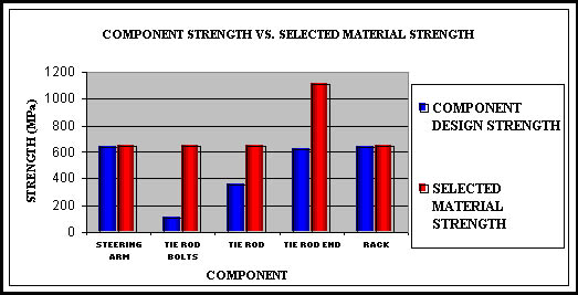
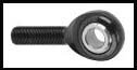
The size of the ends were increased in order to reduce the stress on the component. It was decided to use 3/4” tie rod ends to reduce the stresses felt. AISI 4130 grade steel, or chrome -moly, was chosen for the tie rod ends. This is the strongest material commonly used on tie rod ends and it is commonly available through many part dealers.
The force analysis gives a fairly good estimate of the worst-case forces felt as the wheels turn from 0-30 degrees in front and 0-15 degrees in the rear. From these values it was determined that the largest stresses are felt when the wheels are at their maximum point of travel. The system designed is expected to be more than capable of handling our worst-case scenario. It is hoped that these conclusions will be confirmed during the testing phase.