Operations Manual
Introduction
The Solid Ox System was developed in order to evaluate the performance of solid oxide fuel cells (SOFC’s) manufactured in the Materials Science department at the FAMU-FSU College of Engineering. The testing facility has been developed to test three cells simultaneously. The secondary goal of the system is to demonstrate the working principles of solid oxide fuel cells. The system consists of a ceramic housing, integrated air and fuel flows, a high temperature ceramic heater, electrical connections, and sealing elements. Together, these components are used to measure the electrical output of the cells, combine these outputs, and to obtain current-voltage characteristics of the individual cells.
This document serves as an operations manual for the Solid Ox System and will explain the following areas:
1. Working principles of SOFC’s,
2. Precautions for operation
3. Component List
4. System setup
5. System Operation
6. Troubleshooting
If there are any issues not addressed in this document, please contact any of the following members of Team Solid Ox:
Angelo Caruso: Caruso@magnet.fsu.edu
Amy Valenzuela: valenam@eng.fsu.edu
James Finley: finleja@eng.fsu.edu
I. Working principles
SOFC’s have operating principles similar to those of batteries, in that they are solid-state devices that convert chemical energy into electrical energy. This chemical energy is obtained from the incoming hydrogen and oxygen gas flows and their reaction with the anode and cathode. This reaction only takes place at elevated temperatures (above 800°C), which necessitates the use of a high-temperature heating device.
The three main parts of the fuel cell electrode/electrolyte assembly are the anode, cathode, and electrolyte. On the cathode side of the cell, incoming air reacts to form oxygen ions. These ions are conducted through the electrolyte, to the anode. The fuel (in our case hydrogen) enters on the anode surface of the fuel cell and reacts with oxygen ions to produce water, in the form of steam, and free electrons. Free electrons flow from the anode to the cathode in an external circuit. The electrons sustain the reduction reaction at the cathode, and the cycle repeats itself.
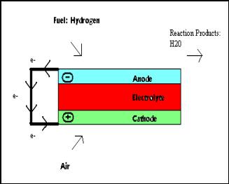
Figure 1.1 Fuel cell operating principles
II. Precautions
A. Hydrogen
a.
When working with hydrogen or any flammable substance,
utmost care must be exercised in the prevention of fire and/or explosion.
i.
Do not operate in enclosed spaces where vented hydrogen
could accumulate.
ii.
Ensure that all electrical connections are adequately
insulated, to prevent possible gas ignition by spark.
iii.
Vent excess hydrogen appropriately.
iv.
Check seals for gas leaks prior to system operation
v.
Flow helium through the system and use a helium
detector to find leaks
B. Ceramics
i.
Handle with care: Ceramics are brittle and may fracture
ii.
Do not over-compress assembly (see section 4.3 for
instructions)
C. Heater
a.
Subassembly surface should not come in contact w/
heater
vi.
Contact with the surface will cause very high local
temperatures and could lead to heater failure or fracture of ceramic.
vii.
Do not exceed a gas flow rate of 5 ft^3/hr or a
temperature of 1200°C
III. List of Components
A comprehensive list of all parts needed to build the test facility is given in Appendix A. The parts are listed with dimensions, supplier, part number, and price. If there are any further questions on the parts listed please feel free to contact Team Solid Ox.
IV. System Setup
The system setup of the test facility works from the inside out. Pictures of all the components can be found in Appendix A and are referred to by the letter listed below.
A. Component list, by subassembly
i. Solid Oxide Fuel Cells (A)
ii. Wire Mesh (B)
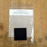
iii. Metal Adhesive (C)
iv. Inconel Wiring (D)
v. Gaskets (E)
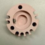
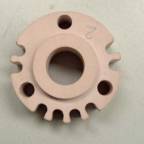
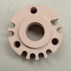
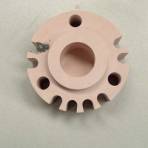
vi. Outer Housing Components (F, G, H, I,)
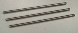
vii. Inconel Threaded Rod (J)
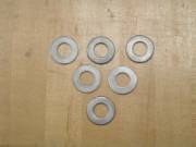
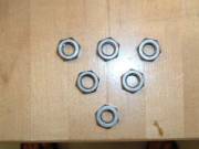
viii. Washers (K)
ix. Nuts (L)
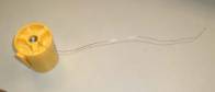
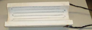
x. Heater (M)
xi. External Circuit (N)
xii. Thermocouple (O)
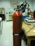
xiii. Oxygen Tank (P)
xiv. Hydrogen Tank (Q)
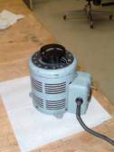
xv. Variac (R)
xvi. Insulation Bricks (S)
a.
Electrical Connections
· Adhere a wire mesh (B) to the front and back surfaces of each solid oxide fuel cell (A) using the metal adhesive (C). Allow the adhesive to fully dry (12 hours). An inconel wire has been permanently attached to the center of three outer housing components (F, G, H,). Connect each wire mesh (B) to the inconel wiring (D) using the metal adhesive (C). Allow the adhesive to fully dry (12 hours).
b.
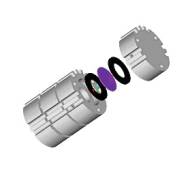
Inserting the Cell
· On three of the outer housing components (F, G, H) there is a recess 0.74” in depth. Place a gasket (E) in the recess of each of these outer housing components. Next, place the fuel cell/wire mesh in the recess. Finally, place another gasket (E) in the recess on top of the fuel cell and wire mesh. Figure B-1 depicts this step of the assembly.
c. Outer Housing Stack
· After putting the gaskets and fuel cells in the F, G, and H outer housing components, stack all of the outer housing components on top of one another. The outer housing component F will be on the bottom and I will be on the top. Makes sure that the geometries align on all of the components.
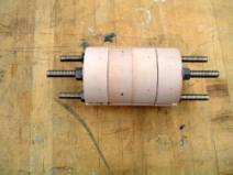
d. Compression
· Take an inconel threaded rod (J) and put it through each of the three large holes in the housing components. Carefully pick up the outer housing such that the inconel rod comes out equal distances on both ends of the fuel cell stack (refer to Figure B-2). Put a washer (K) on both sides of each rod. The washer should rest against the outer housing components. Screw nuts (L) onto each side of the inconel rod. Incrementally torque each bolt to 7 ft-lbs. Do not exceed this value or failure of the ceramic components may occur.
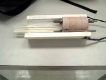
e. Heater
· Place the compressed outer housing stack in the heater (M). The stack will rest on a wire bed that lies in the heater. The wire bed should suspend the stack 0.5” from the heater surface. The stack should rest with the 4 consecutive gas inlets on the bottom (refer to the orientations of Components F, G, H, I shown in Appendix B). Align the back of the outer housing component end of the heater such that the gas inlets on the bottom of the stack run the full length of the heater (refer to Figure B-3).
f. Electrical
· External circuit: Connect the inconel wiring (D) that comes out of the three outer housing components (F, G, H) to the external circuit (N).
· Connect the thermocouple (O) that comes out of two of the gas outlets to the multimeter, and set it to type K thermocouple mode.
· Plug the variac (R) into the wall. Connect heater (M) to the variac (R).
g. Gas Connections
· Connect the first and third gas inlets (refer to Figure 1.3) to the Oxygen Tank (P) using the flexible plastic tubing. Connect the second and fourth gas inlets (refer to Figure 1.3) to the Hydrogen Tank (Q) using flexible plastic tubing.
h. Final Heater Assembly
·
Cover the top of the heater
and outer housing stack with the insulation bricks in the proper configuration
(S).
V. System Operation
A. Seal Check
·
After following the instructions for system setup,
connect the gas inlets to a helium source and begin flow of He. Keep the flow rate of Helium at 5
ft^3/hr. Use a helium sniffer to check
if there are any helium leaks along the length of the assembly.
B. Operation
· Turn on the variac to 90 Volts
· Wait for the heater to warm up to a constant temperature of 800°C
· Carefully turn on the air and hydrogen supply by twisting the valves on each tank to the left. A flow rate of 5.0 ft^3/hr is desired.
· Carefully monitor the flow rates and temperature to make sure they do not exceed 5.0 ft^3/hr and 1000°C.
· Do not leave the system unattended.