Introduction:
The Mary Brogan Museum of Arts and Science (MOAS) has a mission
to offer inspiring educational experiences for people of all ages
using links between science, mathematics, technology and visual
arts. The Brogan Museum has always searched for new ways to stimulate
the interest in and understanding of science. MOAS has currently
proposed an energy-themed public education program focusing on
the cost of electricity, rising price of fuel for vehicles and
alternative sources to provide environmentally sound energy. In
doing this, the museum has established the interest of working
with the FAMU-FSU College of Engineering to create a wind-turbine
demonstration that will educate the public on wind as an alternate
source of energy.
The wind energy demonstration for the museum has several important
specifications and constraints that need to be satisfied. The
museum attracts guests of all ages, including the youth that attend
the local school systems. The Brogan Museum believes these future
thinkers of America are the main target audience. With this in
mind, the design needs to concentrate on attracting and keeping
the interest of the younger visitors as well as being educational
enough to teach something new to the adult visitors. The key to
keeping the younger museum visitors’ interest is to make
the exhibit interactive, giving the children the chance to visualize
physical effects. The design needs to be able to be viewed from
more than one side that will enable a group of visitors to interact
and learn from the exhibit at the same time. As well as multiple
viewing angles, the design should also make all of the important
moving parts visible. Since children are the main audience, the
science and engineering aspects of the design need to be explained
in simple terms, and should appeal to several different learning
styles. The expected lifetime of the wind energy exhibit is several
years; therefore, the design should be durable and require very
little maintenance. However, the most important specification
is the safety of the future visitors of the final exhibit. Once
these specifications are met, an attractive professional looking
museum exhibit will be produced.
The Brogan Museum’s specifications are not the only considerations
that have found their way onto the design table. Other engineering-based
ideas and components need to be implemented into the design in
order to help demonstrate what is actually happening. A device
to monitor and display the wind direction would help depict the
amount of wind required to generate power from a turbine. The
use of a diffuser to accelerate the wind’s velocity and
the application of a mesh screen or honeycomb to regulate the
flow of the wind will also be needed in the design to insure a
laminar flow of air. A power output device needs to be installed
to inform the audience of the amount of power that can be produced
using wind energy. The idea of comparing two different types of
wind turbines has also been discussed. Another idea to aide in
understanding the principles of the exhibit includes a device
to measure the rotational speed of the wind turbine. Although
these components and ideas are not essential to the design, they
will help convey the ideas and information to a wide variety of
museum-goers.
With all this in mind, Wind Energy Systems Inc. has been created
to design and fabricate the wind energy demonstration. Wind Energy
Systems Inc. is comprised of five FAMU-FSU College of Engineering
students in their senior year of study. The members of the company
are Nicholas Bembridge, Victor Fontecchio, Bradley Kroger, Michael
Sheehan and Suzanne Shepherd. Dr. Chiang Shih has also taken on
the role of sponsoring the group. With these specifications, resources
and ideas, the members of Wind Energy Systems Inc. have developed
the following designs to be considered for the wind energy demonstration
for the Mary Brogan Museum of Arts and Science.
First Design Generation:
The first design that Wind Energy Systems Inc. came up with was
a simple wind energy exhibit using a hand-crank as the power source.
The hand-crank would power a wind generation fan that would then
cause a windmill to turn and power a DC motor. This DC motor would
supply electrical energy to a power meter so that children could
see the energy output by wind they created with the hand-crank.
In order to make the exhibit more interactive to kids, the windmill
would have an adjustable angle of attack to show different efficiencies
of the exhibit. This design of an interactive science museum exhibit
would have been ideal, but completely unrealistic. The hand crank
would not be able to supply enough energy to a fan that would
create enough wind to power the rest of the exhibit. The adjustable
angle of attack on the windmill was deemed too complex of a task
to complete in time when considering what needed to be done with
the rest of the project.
Figure 1: Basic model of original
design of wind energy exhibit with hand-crank
This initial design is a rough estimate of what the final project
will look like. After making this sketch, the pros and cons of
the concept were evaluated. The main components of the design
that were evaluated were the hand crank, fan, turbine, power strip,
size, casing, and angle adjustment dial. It was agreed that the
hand crank would be removed. The power needed to generate the
necessary wind speeds for the fan is too large to be generated
by a simple hand crank. Even though this device makes the exhibit
more interactive, an electric fan will replace the hand crank.
Table 1 below gives a list of these pros and cons for the first
design.
Table 1: First Design Evaluation
|
Component |
Pro |
Con |
Reasons/Adjustments |
| Hand
crank |
|
X |
Unrealistic
due to the amount of wind that needs to be produced |
| Fan |
X |
|
Essential
to project, but flow needs to be distributed evenly |
| Turbine |
X |
|
Turbine
is necessary to generate power. Different types of turbine
designs will be considered. |
| Angle
Adjustment Dial |
X |
|
Helps
to describe how important the angle of attack is to the project.
Will help to make the project more hands on. |
| Power
Strip |
X |
|
Necessary
to give a visual depiction of power output |
| Size |
X |
|
Concurs
with the museums initial outlines for the amount of space
the project will be given |
| Casing |
X |
|
The
clear plastic will allow for visualization from all sides;
however, actual assembly of casing is still undecided |
Second Design Generation:
In the second phase of design, several changes were made to overcome
the flaws of the first design. The first item was to remove the
hand-crank. By making this change, something needed to be added
to the design in order to make the exhibit more interactive. The
wind generation fan to be selected would have a motor that is
able to plug into any standard outlet and was specified to be
able to have variable settings to create different wind velocities.
It was also determined that a display of the velocity of the wind
be added to the design. The idea of having two different types
of wind turbines was also implemented; one of the turbines was
to have a vertical axis, while the other would have a horizontal
axis. The idea was that having two wind turbines operating under
the same conditions would demonstrate differences in efficiencies.
As shown in the Figure 2 below, it was proposed that the two
wind turbines sit on a turntable so that observers of the exhibit
could choose which turbine they wanted to operate and see the
power output change as the turbines were moved in and out of the
air flow. Unfortunately, by having the wind turbines on a turntable,
it would be harder to ensure that the wiring would not become
unattached or tangled by the constant rotation of the turntable.
Another flaw in this design is that the plastic casing, shown
to be curved, would be incredibly more expensive than the budget
would allow. The power meters, which are not displayed in the
figure, would also be hard to place on a design like this.
Figure 2: Second model of wind-energy
exhibit with turntable design.
| Component |
Pro |
Con |
Reasons/Adjustments |
| |
|
|
|
| Fan |
X |
|
Electric
fan will be used to output more power |
| Anemometer |
X |
|
Gives
a concept as to the velocity of the wind hitting the turbine |
| Turbine
Variation |
X |
|
Displays
differences in efficiencies of turbines |
| Turbine
Turntable |
|
X |
May
tangle up wiring or other internal components when twisting |
| Power
Meter Display |
|
X |
Cannot
be displayed on this model in a visually appealing way |
| Circular
Plastic Casing |
|
X |
Too
expensive to fabricate for this exhibit |
Third Design Generation:
The third design for our Wind Energy Exhibit for the MOAS was
a further modification of the previous two designs. In this design
after meeting with our sponsor as well as the director of the
museum we decided that it would be a good idea to have two different
types of wind turbines to demonstrate more than just one type
of energy generation. The case that surrounds and protects the
exhibit will still be a hard clear plastic that would cover both
the sides and top of the display. To show the power that would
be generated by the different wind turbines, there would be a
type of visual power meter that consisted of light bulbs lined
vertically that would light up sequentially with power; the more
power the more bulbs that would light up. The air supply to the
exhibit would be from a fan mounted on the end, the flow would
be directed using a type of nozzle as well as a plastic mesh or
honeycomb to try and equalize the flow throughout the chamber.
All controls in this concept will be in front of the exhibit.
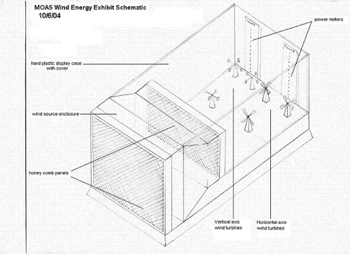
Figure 3: Third model of wind-energy
exhibit utilizing a wind farm
This design is very close to a final, agreed-upon design; however,
there are components that need to be evaluated and redesigned.
Below in Table 3 these components’ pros and cons have
been evaluated.
| Component |
Pro |
Con |
Reasons/Adjustments |
| |
|
|
|
| Plastic
Mesh/Honeycomb |
X |
|
Equalizes
and distributes the flow evenly throughout chamber |
| Visual
Power Meters |
X |
|
Visually
depicts power output to give a better comparison |
| Rectangular
Casing |
X |
|
More
realistic and less expensive than circular casing |
| Turbine
Wind Farms |
|
X |
Focus
on one turbine of each design instead of three |
Final Design Generation:
The group again met with the director of the museum as well as
a group this design was rejected as a whole but many of the ideas
would carry through to the next design. The biggest design change
is that the case of the exhibit will be made of welded square
tubing, with plastic pieces used to fill the openings, instead
of the plastic having to support its own weight. There will still
be multiple wind turbines but due to complexity and cost there
will only be one of each type. In this design the power meters
are in the path of the flowing air, this will cause problems with
the exiting of the fluid. To end this problem it was proposed
to move the power meters to the base of the exhibit next to the
controls. The idea of having many of the sides clear was the best
option, but the director of the museum wanted to have writing
about the exhibit on the wall facing the audience making it almost
impossible to have the back wall clear. A good basic concept for
the basis of the wind exhibit is shown below, and many of the
concepts have been used in the following design; however, many
have been modified. An artist rendition of this fourth iteration
of the design is shown in Figure 4.
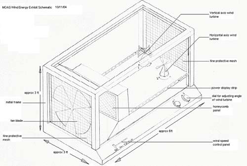
Figure 4: Fourth model of wind-energy
exhibit utilizing two windmill types and a steel frame
Figure 4 depicts the final design for the project. This project
will be enhanced with color and visual aides in order to make
it appealing to all viewers. The wind turbines will be mounted
on turntables to utilize different attack angles for the airflow,
which will increase the level of interaction. The displayed
model will be mounted on a base approximately 33 inches high
in order to accommodate on-lookers of most heights. All of the
final components are outlined below in Table 4.
| Component |
Reasons/Adjustments |
| |
|
| Casing |
Composed
of welded tubing to hold clear plastic sheets |
| Wind
Turbines |
Two
different types will be used in order to display different
efficiencies |
| Power
Meters |
Placed
horizontally along exhibit so as to not interfere with other
components |
| Size |
Final
design will fit into designated space |
| Angle
Adjustment |
Will
vary angle of attack of turbines in order to further display
efficiency differences |
| Anemometer |
Display
wind velocity of the fan |
| Fan |
Powered
by electricity and varied by a dial to create different flows |
| Plastic
Mesh/Honeycomb |
Creates
an even flow to be distributed throughout the casing |
| Exhaust
Wire Mesh |
Allow
exhaust wind to flow out of the casing |
Conclusion:
The next steps for the group are to compile a formal proposal
for the MOAS. This proposal will include a budget, plan for construction
of the exhibit, list of needed supplies, list of possible manufacturers,
and engineering drawings. The proposal will be presented to the
museum in early November. Once the initial proposal has been presented
and approved, the group will assist the museum in contracting
another proposal in order to receive funding for the project.
Through meetings with the group sponsor, the museum coordinators,
and members of the group, a final design for the wind-energy exhibit
has been created and approved. The group began by first evaluating
the product specifications, needs assessment, and project scope.
The group’s final goals are still the same, but by continuous
scrutiny and evaluations of the proposed designs, the members
were able to choose a final design that meets the needs of the
project in the best and most fitting way possible. In addition
to the initial considerations, the museum staff also reviewed
the final design as well as the appearance of the project.
The collaboration of the group and the museum staff has led to
a successful and creative design selection. The project is educational,
interactive and safe for museum-goers of all ages. The final design
utilizes several angles from which to view the exhibit, as well
as two types of wind turbines in order to display the difference
between efficiencies for the vertical and horizontal axes. Not
only are two different wind turbines used, different angles of
attack for the air flow will be implemented to further increase
interaction with the exhibit as well as understanding of the effects
of wind energy. The display will be visually appealing and professional
looking in order to convey a confidence about the principles within.
All of these ideas together combine to create a successful wind
energy demonstration. With these concepts and careful planning,
the resulting project will be a lucrative exhibit that provides
a deeper understanding about wind energy.

|