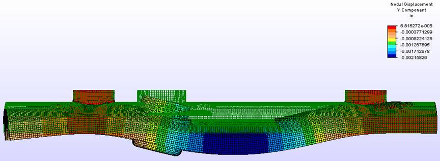
Figure B-1: The Carbon Fiber/Aluminum Prototype under the
weight of an MK – 82 bomb doing an eight ‘g’ maneuver
(4000lbf) is shown above
with a
color coordinated nodal displacement survey in the Y-direction with an exaggerated
curvature and original mesh outline; units are inches.
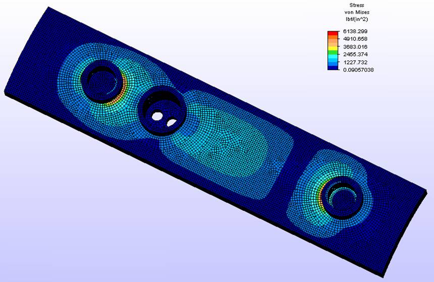
Figure B-2: The
Carbon Fiber/Aluminum Prototype under the weight of an MK – 82 bomb and eight
‘g’ maneuver is shown above computing
the Von Mises stress; units are psi.
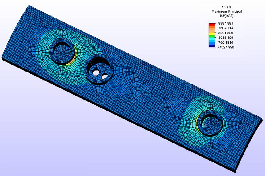
Figure B-3: The
Carbon Fiber/Aluminum Prototype under the weight of an MK – 82 bomb and eight
‘g’ maneuver is shown above analyzing the
maximum principal stress; units are psi.
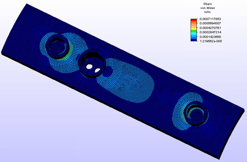
Figure
B-4: The Carbon Fiber/Aluminum Prototype
under the weight of an MK – 82 bomb and eight ‘g’ maneuver is shown above
computing the
Von Mises strain; units are
in/in.
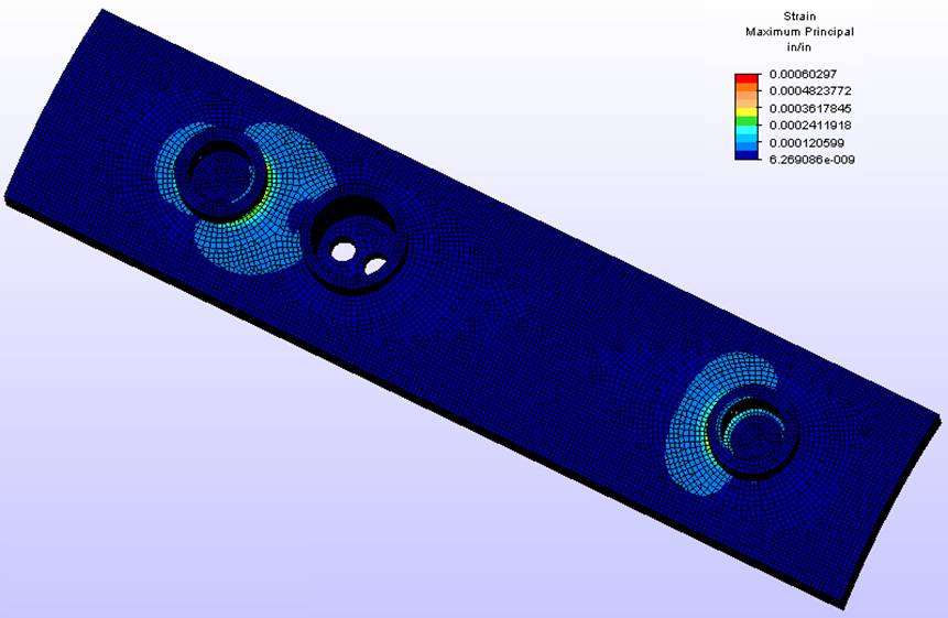
Figure B-5: The
Carbon Fiber/Aluminum Prototype under the weight of an MK – 82 bomb and eight
‘g’ maneuver is shown above analyzing the
maximum principal
strain; units are in/in.
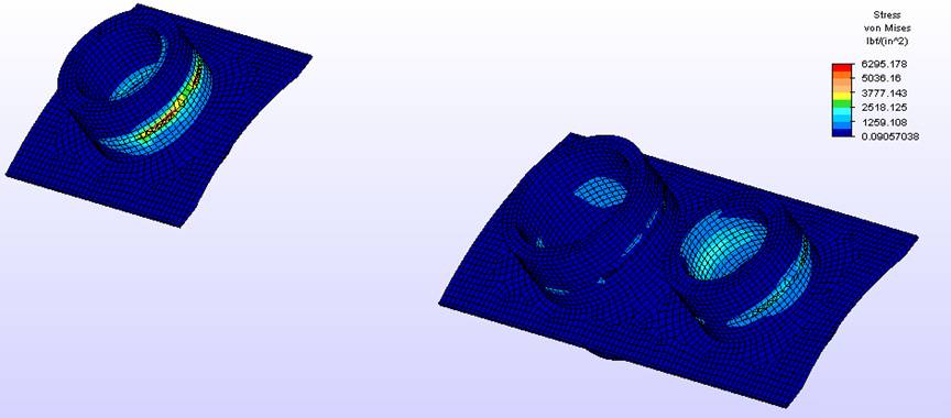
Figure B-6: The
Aluminum inserts under the weight of an MK – 82 bomb
and eight ‘g’ maneuver is shown above computing the Von Mises
stress;
units are
psi.
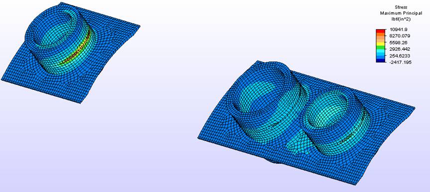
Figure B-7: The
Aluminum inserts under the weight of an MK – 82 bomb
and eight ‘g’ maneuver is shown above computing the maximum
principal
stress; units are psi.

Figure B-8: The
Aluminum inserts under the weight of an MK – 82 bomb
and eight ‘g’ maneuver is shown above analyzing the Von Mises
strain;
units are
in/in.
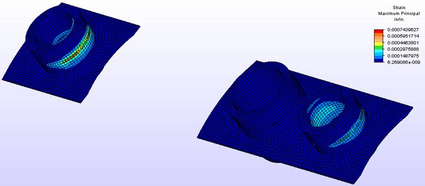
Figure B-9: The
Aluminum inserts under the weight of an MK – 82 bomb
and eight ‘g’ maneuver is shown above analyzing the maximum
principal
strain; units are in/in.
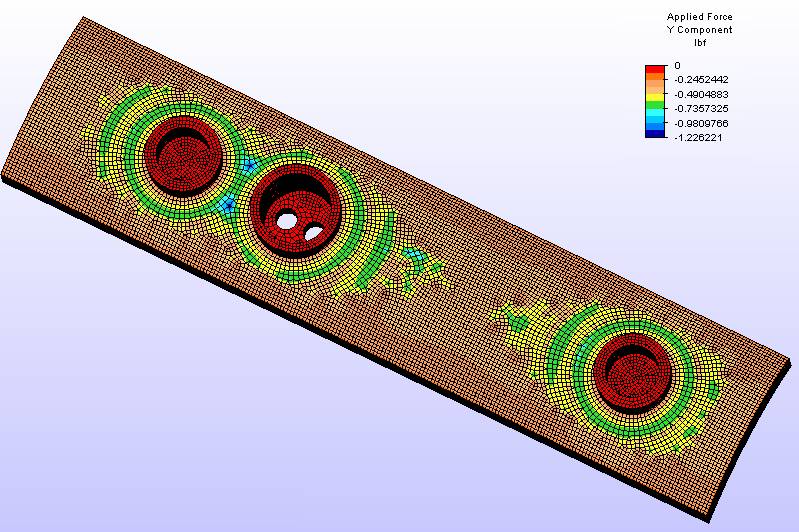
Figure
B-10: The Carbon Fiber/Aluminum
Prototype under the weight of an MK – 82 bomb and
eight ‘g’ maneuver is shown above in applied
force in
the Y-direction; units are lbf.
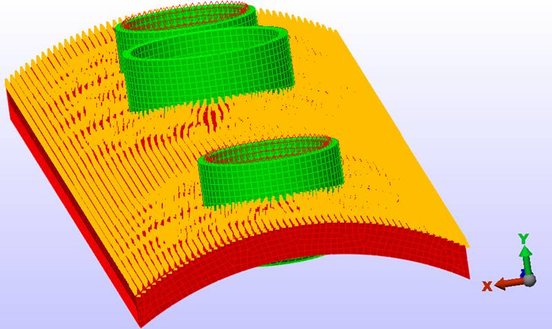
Figure B-11:
The Carbon Fiber/Aluminum Prototype shown above was first grounded by
the two aluminum lug inserts (red triangles) then an
evenly
distributed load of 39 psi was placed on the top
surface (yellow arrows) and finally the FEM program “Algor”
engineered the magic.