Most importantly, the team’s goal is to fulfill the sponsor’s needs. Need number one is the integration of the global positioning system (GPS) into the navigation system of the lawnmower. Need number two is to eliminate the vibration caused by the 1.5 pound blade rotating at 3000rpm. As the blade rotates, it forces the sheet metal to bend back and forth thus causing the rest of the mower to vibrate. Research for the project consisted of different options for cutting grass that would cause the least vibration possible. It was unnecessary to research electronic components to buy because many of the components will be reused from last year.
Another goal, since the mower is going to competition, is to make the mower a more viable competitor. To do this the mower must cut as much grass as possible in the shortest amount of time and also use as little energy as possible. To accomplish this goal, the most obvious improvement is to increase the cutting area of the mower. The previous design used a relatively small 9.5” blade. Using a small blade means making more passes with the mower to cut the same amount of grass, which is not very energy efficient.
Taking these things into consideration, we compiled a list of various ideas for concepts, and weighed each concept to find which was the most viable.
The first idea simply extends the cutting blade to cover the entire width of the chassis (see Figure 4). This design presents a few problems in terms of weight and power requirements. A longer blade will certainly be heavier and require more torque and power to turn. The total weight estimate with a longer blade is about 76 pounds and would consume approximately 30 amps (see Appendix B for calculations). A longer blade might also increase the vibration problem due to more rotating mass. There is a possibility that adding vibration damping to the chassis could solve this problem, although there is no way to tell until it is tested. The need for vibration damping could be lessened if we could eliminate or greatly reduce the source of the vibrations.
Figure 4: Longer Blade Concept
One solution was to use the idea of a string trimmer. It seems to be ideal because it reduces the overall weight, and it can potentially eliminate the vibration problem that the metal blade created, as it would almost eliminate all rotating mass. A string trimmer design is also less affected by mowing over rocks, sticks, or roots. Mowing over these with a metal blade could damage the mower or injure the operator or a bystander by sending the debris flying in the air. The string trimmer design offers much more safety in that aspect.
Since the driving motors placed side by side are 26” wide, and it is desired to have a 2” overhang on each side, the total cutting width of the mower will be designed to be 30” wide. With a cutting width of 30”, it is necessary to consider dividing the cutting width into multiple cutting circles since it would be virtually impossible to have a single cutting head with string that long. We also considered some sort of chain or metal string for the trimmer but these options seem more dangerous than the string and safety is a high priority.
The next step is to determine how many cutting circles are necessary to optimize the performance. It is necessary to determine the cutting width of each circle to determine its technical feasibility.
To cover half the chassis width (13”), plus 2” inches on either side would lead to a diameter of 17” for each circle (see Figure 5). Research of commercial string trimmer found that no electric string trimmer’s cutting width exceeded 15”. The problems of motor torque and the cutting cord breaking would be worse at 17” than at a lesser diameter. Since we want this mower to be relatively maintenance free, we don’t want to have to replace broken cutting line very often. The motor that turns the cutter would also require more torque and, consequently, more power for a larger diameter cutting circle.
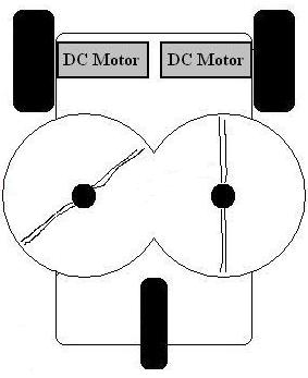
Figure 5: String Trimmer Concept with Two Cutting Circles
With three cutting circles (see Figure 6), the design would need two 12” circles and one 10” circle. The two 12” circles would be on the outside with the 10” circle in the middle. The heads would be staggered so that none of the strings would collide during operation. These smaller diameter circles are within the scope of commercially available string trimmers. With smaller cutting circles the cord on each head will theoretically break less often, as the tip velocity is a lot less for a given rpm. The motors that will turn the cutting heads will require less torque to cut the grass. This will allow us to use smaller motors that don’t require as much power. This option for the string trimmer concept seems to be better than the option with 2 cutters for the reasons outlined above. It consumes about 36 amps and weighs around 69 pounds (see Appendix B for calculations).
Figure 6: String Trimmer Concept with Three Cutting Circles
An idea for powering the cutting heads is to have a belt drive pulley system that will use one motor to drive all the cutting heads. The system would require a single large motor with lots of torque. A downside to having a pulley system is that all heads become dependent on each other. If one pulley fails, then the whole system stops working. Supposing that one pulley became tangled and stopped rotating, the belt would either slip, causing excess heat and wear due to friction, or it would cease up and stop rotating- possibly damaging the motor. With separate motors for each head, one head could get jammed and the rest of the system would still operate.
In terms of taking up space, the belt of the pulley system would occupy space on the chassis that could otherwise be used for mounting our electronic components. In terms of manufacturing, it seems that a pulley system would be much more difficult to construct than simply mounting three motors. The weight of one large motor, three pulleys and a belt would be greater than or equal to the weight of three smaller motors. On top of that, a pulley system would have to be properly aligned or problems would result. From the preceding discussion, independent motors will be used if the string trimmer concept is selected.
Another idea was to use the blade of a hedge trimmer. It would consist of a sliding cutting tool that translates back and forth in order to cut the grass. The apparatus would be installed under the mower within the wheelbase. However, as seen in the picture in Figure 7, there would have to be some sort of covering over this cutting mechanism to make it safe. Another concern outside of safety is where to mount the motor. As seen in the figure, hedge trimmer’s motors are mounted on one end of the blade, making mounting in our configuration virtually impossible. Another negative aspect is the fact that it would require maintenance. The blades would need to be lubricated regularly to keep them operating at their peak performance. This system would consume about 33 amps and weight around 71 pounds (see Appendix B for calculations).
Figure 7: (Left) Hedge Trimmer Concept, (Right) Picture of a Hedge Trimmer (www.homedepot.com)
This concept involves having the bottom portion of a Reel lawnmower attached to the rear portion of the current lawnmower as seen in Figure 8. This came together because it is very basic and simple option. The platform with its GPS would guide and drag the attached lawnmower behind it. The cutter can be used without modification and attached to the chassis, so no moving parts would need to be designed. This device would require no electricity to operate. However, this idea presented major weight and size issues. A major concern about this concept is how much force and power would be required to pull the apparatus due to its added weight. Reel mowers advertised on ebay.com weighed between 19 and 35 pounds. This would not present much a problem if only one was to be used, but two would need to be attached in order to have a width comparable to the chassis width. The cutting widths of reel mowers range between 16” and 20” while the desired cutting width of our mower is about 30”.
This concept presents problems in terms of combining it with the current platform. It is not quite clear how the current steering mechanism of the mower would be affected by towing two reel mowers as shown in the diagram. Since the reel by itself draws no power from the batteries, power consumption for this design is a mere 23 amps, however the weight is about 94 pounds (see Appendix B for calculations). The drive motors would require more power to pull the heavy reel mowers.
Figure 8: (Left) Reel Mower Concept Drawing (Right) Picture of a Reel Mower (www.homedepot.com)