
|
CATALYTIC TEMPERATURE SENSOR |
|
CUMMINS II |


|
Recommended Solutions |

|
Recommendation for Short Term Solution
In phase one it was determined that a platinum wire wound ceramic class B RTD element would be best suited for this application. After testing both the Omega and Minco RTDs, this recommendation still stands. From these tests the Omega RTD usually performed best, however this was not true in all cases. The temperatures reached in testing were significantly less than the operating temperatures of the exhaust systems attempting to be simulated. Due to this, further testing would be required with both RTD elements in order to decide which would perform best in actual applications.
Recommendation to be Researched and Developed
Coupling of Optical Fibers and Infrared Temperature Sensors
The coupling of optical fibers with Infrared temperature sensors provides superior temperature sensing capabilities. While optical elements have been used for years with infrared sensors, fiber optics had not been considered as a practical technology to combine with infrared sensors due to the fact that they are made of plastic or glass. With plastic and glass being opaque in most the infrared spectrum region, it was thought that the coupling of the two defied laws of physics. Recent development, however, has proved otherwise, and the pairing of these two has revealed a vast array of new temperature measurement technology.
Fiber Optic Technology
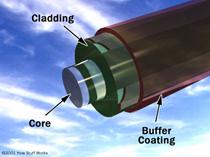
Three separate layers make up a single optical fiber. These layers are displayed in Figure 10.3 and are known as the core, cladding and the buffer coating. The core is made up of thin glass or plastic. This is where the light will travel. The optical material that surrounds the core, reflecting light throughout the fiber, is known as the cladding. Surrounding these materials is a protective buffer coating preventing moisture or damage from being inflicted on the fiber. Figure 10.3 shows how light is transmitted through a single optical fiber.
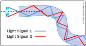
Figure 10. Layers in an single optical fiber (left) and light reflection inside (right)
These fibers are bundled together in a jacket, resulting in an optical cable containing hundreds, sometimes thousands of single fibers. The ends of the fibers are generally polished or contain a transmitter such as a lens to achieve a clear angle of acceptance. As one would expect, these cables are only capable of transmitting as much energy as it can absorb. Consequently, the length of a cable required to transmit a signal is directly related to the temperatures that need to be translated. For example, lower temperatures require shorter cables. Impurities in the glass or inability to effectively transmit wavelengths through the cable entirely results in error. In systems utilizing optical fibers, accuracy is, therefore, dependant on a design unique to each system.
Infrared and Fiber Optic Technology in Application
In application, the combination of these two technologies requires accurate transmission of radiation from the source to the infrared sensor. Successful transmission of these wavelengths results in extremely accurate temperature sensing capability.
In automobile application, a high temperature epoxy is used to join cables, or bundles, each containing hundreds or even thousands of optical fibers if necessary to absorb all the radiant energy in the target location. The ends of the fibers are typically polished to ensure a clear angle of acceptance and to decrease losses due to irregularities on the surface. To measure the surface temperature of the brick in a catalytic converter, the fiber optical bundles would be fixed on its target, transmitting all energy emitted to an infrared temperature sensor outside the catalytic converter.
At this point, infrared sensors are largely expensive for mass production and application in catalytic converters. Though their cost is an associated downfall of this method, it may be possible in a few short years to minimize costs and utilize a combination infrared/fiber optic technology for mass production in vehicles. Currently, the combination of these two technologies is used in extremely high temperature sensing in expensive systems where extreme temperature regulation is necessary. Systems where this application is advantageous over the cost can be found in aircraft and other sophisticated technologies. For now, the method is ideal for testing or monitoring instruments at extreme accuracies, unattainable any other way.
While Cummins currently uses thermistors in diesel engines application to monitor catalyst temperatures, technology continues to advance at a fast rate. New methods of constructing RTD elements and new sheath materials are allowing for them to be used in applications never before possible. Resistance temperature detectors are steadily improving in almost all categories, specifically response time and temperature ranges. With continued testing and development of these elements, they may soon appear in some of Cummins’ trucks.
Determining temperature from infrared radiation with the help of fiber optics is still an extremely difficult and expensive method. Though it is already currently used in some applications, it will be a long time before it is feasible for production in vehicles. Continued research and development is a must for a company like Cummins, and fiber optics appears to be a promising investment that will be used in the future for application in catalytic temperature measurement in vehicles. |