
|
CATALYTIC TEMPERATURE SENSOR |
|
CUMMINS II |

|
BACKGROUND RESEARCH
Cordierite Catalytic Converters
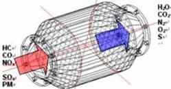
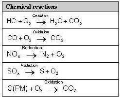
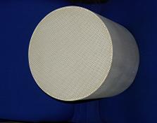
Vehicle exhaust systems require a device known as a catalytic converter (Figure 1.1) to chemically change pollutants such as hydrocarbons (HC), Nitrogen oxides (NOx), carbon monoxide (CO), and other impurities into harmless substances acceptable to the environment. Essentially, this reaction occurs as a combination of exposure to high temperatures and flow rates. The result is an emission of Carbon dioxide (CO2), Nitrogen (N2) and water vapor into the atmosphere. The catalytic converter diagram below displays the chemical reactions that take place in the converter.
Figure 1.1 Typical catalytic converter
Figure 1.2 Chemical reactions that occur in a catalytic converter
In this case, a cordierite catalytic converter (Figure 1.3) is used to oxidize pollutants. Porous cordierite is commonly used in catalytic converter application and functions well at high temperatures, with a melting point of 1400°C. Typically, these converters achieve maximum efficiency through high cell densities of roughly 300-400 CPSI (cells per square inch).
Theoretical Background/Functionality of Temperature Sensors
Engineers utilize a wide array of sensors to measure temperature. These sensors include thermocouples, thermistors, resistance temperature detectors, infrared radiators, change-of-state devices, liquid expansion devices and bimetallic devices. Thermocouples and thermistors are the standard detectors utilized in exhaust systems. Resistance temperature detectors (RTDs) have recently become advanced enough for practical application in exhaust systems. Therefore these three sensors will be examined.
Thermocouples
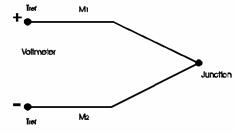
Thermocouples employ two different types of metals to detect a change in electromotive force (emf voltage) at the juncture of the two metals (Figure 1.4). This electromotive force can be converted to temperature by an electronic control system. Typically, these devices consist of two wires that are welded together at the end. The rise in temperature is consistent with a rise in electromotive force induced. This rise, however, is typically not linear, leading to inaccuracies out of specific ranges. Ranges for these devices are dependant on the metal alloys selected and their calibration.
Figure 1.4: Thermocouple with cold junction compensation
Thermistors
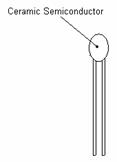
Thermistors measure temperature by detecting a resistance change in a ceramic semiconductor. This detected resistance change has a negative temperature coefficient, decreasing with an increase in temperature. These devices are very accurate, producing extremely sensitive temperature readings over small ranges. In application, however, thermistors are incapable of a linear response extending out of these small ranges, and achieving high accuracy over a larger range is not plausible with out the use of several thermistors. Over a large range, tolerance in thermistors can be extremely poor.
Figure 1.5: Thermistor
Resistance Temperature Detectors (RTDs)
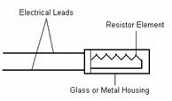
Similar to a thermistor, resistance temperature detectors sense temperature by recognizing a change in resistance correlating with a change in temperature. They differ, however, in that they detect a natural change in resistance of a metal rather than the non-metallic ceramic materials used in thermistors. In essence, these devices capitalize on the fact that most metals change resistance quite linearly with temperature changes. There are two main types of RTDs: wire wound and thin film. Wire wound RTDs typically contain a ceramic core with a thin wire wrapped around it until the desired resistance is reached. Slower response characteristics are associated with this type, while they are capable of achieving rather high accuracies. Thin film RTDs consist of a thin metal coating over a flat, ceramic material. These RTDs are capable of a quicker response than the wire wound elements.
Figure 1.6: RTD element
|

|
RESEARCH |