
|
CATALYTIC TEMPERATURE SENSOR |
|
CUMMINS II |

|
TESTing Procedures |

|
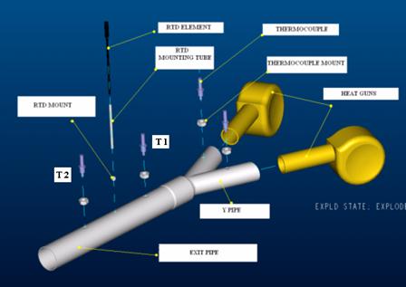
Schematic Setup of Testing System and Components
Placement of the sensing elements is shown in Figure 3.1. These locations allow for both temperature and pressure readings at critical locations in the system itself.
Figure 3.1. Exploded view of the testing system showing placement of all temperature sensing elements.
In design of this system, a modified version of Bernoulli’s equation (Equation 2.1) is used to estimate the head loss in the system to assure that the guns can maintain a sufficient velocity and not overheat. Diameters are chosen based on these calculations and the need to simulate air velocity in an exhaust system while keeping pressure increase to a minimum.
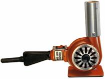
Industrial Heat Guns
Industrial heat guns (Figure 3.2) will provide both heat and air flow at a rate of 23 ft³/min. The exit diameter of the nozzle is 1.75”. By filtering the air flow from two guns into a single pipe, velocity is increased, allowing a simulated velocity as experienced by an element in a catalytic converter.
Figure 3.2. Industrial heat guns provide air flow and heat
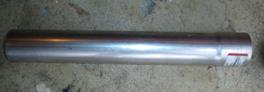
Piping and Insulation
Steel exhaust piping is used and sealed with a flameproof ceramic coating to provide some insulation. The coated and assembled piping network is insulated with to minimize heat loss. The inner diameters of the exit and Y-piping are 2.25” and 1.75”, respectively. Nuts welded to the piping provide mounting for the threaded thermocouples and a 3” insulated steel tube welded upright provides mounting for the RTD probes
Figure 3.3. Exit pipe (left), Y-pipe (center) and flameproof ceramic seal (right)
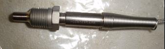
Thermocouples
These thermocouples are type K pipe plug probe sensors manufactured by Omega.com. These thermocouples are built for heavy duty, high temperature sensing application. They are an ideal choice as reference temperature sensors since Cummins wants a sensor capable of achieving the same accuracy as a thermocouple but more durable.
Figure 3.4. Type K pipe plug probe thermocouple
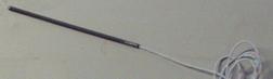
RTD Probes
Both RTD probes contain class B platinum ceramic wire-wound elements. The probes are 6” in length and contain four wires, providing the option for both three and four wire configurations. The element from Minco utilizes a nickel alloy sheath while the element from Omega uses a stainless steel sheath. The elements were both custom made for this application and use 6’ wires.
Figure 3.5: Omega RTD probe (left) and Minco RTD probe (right)
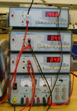
Digital Multi-meters and Constant Voltage Source
Three digital multi-meters allow for voltage readings from each element. The constant voltage source allows for a voltage drop across the RTD element.
Figure 3.6 Digital multi-meters (top 3 devices) and constant voltage power source (bottom device)
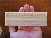
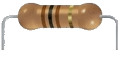
Electrical Components
A breadboard and three 100Ω resistors are required for the three-wire configuration setup.
Figure 3.7 Breadboard (left) and 100Ω resistor (right)
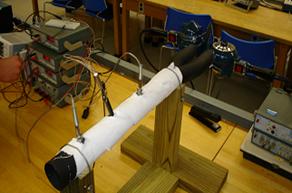
Test Setup Procedures
Figure 3.7 Assembled Testing System
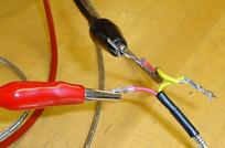
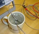
Figure 3.8 Cold junction wiring (left) and ice bath (right)
Wire two thermocouples together as shown in Figure 3.8 to create the cold junction. Be sure the same colored wire from each sensor is connected at the junction point. Attach the loose wires from the thermocouple to positive and negative inputs on the digital multi-meters. Attach heat guns and thermocouples, T1 and T2, to the locations shown in Figure 3.7. Be sure the thermocouples are screwed in tightly and that all holes are plugged. Place the attached thermocouples in an ice bath kept at 0º C during testing (Figure 3.8). Set up the modified Wheatstone bridge displayed in Figure 2.3 using the breadboard and three 100Ω resistors. Attach the power source, multi-meter and RTD element to the Wheatstone bridge. Set the constant power source to 1.5 Volts. Run heat guns at maximum temperature and check thermocouple readings. If the system is set up correctly, readings between T1 and T2 will be approximately 1 mV apart.
Testing Procedures
Perform each Test for both the Minco and Omega RTD elements.
Achieving Steady State at Low and High Temperature Settings
With RTD element inserted, turn heat guns to lowest temperature setting. Take readings from all sensors every 10 seconds until steady state is reached (at least 3 of the same readings are obtained from each multi-meter). Once system reaches steady state, adjust the heat guns to the highest temperature setting and continue taking readings every 10 seconds until steady state is reached.
Maximum Temperature to Ice Bath
With the system at steady state and highest temperature setting, record all three voltage outputs. Remove the RTD element and place in the ice bath. Take your first reading before removing the element and continue taking RTD readings every 5 seconds until 3 of the same readings are obtained.
Ice Bath to Maximum Temperature
5.) Be sure system is fully heated and at steady state. Do this by observing the thermocouple readings to be constant and record these voltages. Remove RTD element from ice bath and insert into the mounting tube. Take the first reading before removing the element and take RTD readings every five seconds until 3 of the same readings are obtained.
Maximum to Ambient Temperature
7.) With the system at steady state and highest temperature setting, record all three voltage outputs. 8.) Remove the RTD element to ambient temperature. Take your first reading before removing the element and continue taking RTD readings every 5 seconds until 3 of the same readings are obtained.
Ambient to Maximum Temperature
9.) Be sure system is fully heated and at steady state. Do this by observing the thermocouple readings to be constant and record these voltages.
10.) Remove RTD element from ambient temperature and insert into the mounting tube. Take the first reading before removing the element and take RTD readings every five seconds until 3 of the same readings are obtained.
Maximum to Ambient Temperature and Back for Specified Time
From steady state at maximum temperature setting, remove RTD element for only 60 seconds and slide back into its mount. When removing the element, use an oven mitt and be sure the element is only exposed to the air. Take the first reading before removing the element and continue to take RTD readings every 5 seconds until the initial voltage is matched.
Repeat step 11, removing the element for only 30 seconds for this run. |