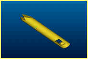
 Figure 4.1.1
 Figure 4.1.2
First Iteration Design Concept Description
Pawl and Ratchet Mechanism/Integration
Integration of the pawl and ratchet mechanism with the joint as a complete design concept involved making sure the mechanism itself could function properly. That meant ensuring the teeth were designed at the correct angle so the pawl could engage properly. The number of teeth was determined by the angle of the increment which was 11.25 degrees, thus allowing for eleven teeth on the ratchet. The pawl extends into the housing. The pawl is engaged and disengaged with a spring and actuator.
 Figure 4.1.1
 Figure 4.1.2
Housing
The housing was based off the current housing for the KingPin Lock, thus able to interface with the KingPin bars. Modifications were made for bushing placement. The housing consists of three main components. The middle housing (figure 4.2.1) accommodates the pawl and spring. The lever for actuation is on the side. It interfaces with one bushing for the outer housing (figure 4.2.2), and a second bushing for the gear hub (figure 4.2.3). The outer housing is an enclosure for the ratchet and contains three holes for the gear hub to be pressed in it. The gear hub consists of one piece with an enclosure and the ratchet. There is also an indentation for the bushing. The three pins that protrude from the gear hub are pressed into the outer housing. This connection ensures any unwanted movement from the housings.
 Figure
4.2.1
  Figure
4.2.2
 Figure
4.2.3
Bearing Type and Placement
Bearings:
The design includes two thin, plastic bearing, which are incorporated to avoid all metal to metal contact (figure 4.3.1). The bearings are also necessary to prevent any axial and radial motion within the joint. One bearing is located between the ratchet and the middle housing. The second bushing is preventing contact between the middle and the outer housing. The bearings are currently manufactured by injecting the plastic into a custom designed mold. To reduce the fabrication of different parts, as well as the cost of machining two custom made bearings, only one type of bearing was used. All grooves and protrusions on the ratchet gear backing and the outer housing were altered to house the bearings chosen.
 Figure
4.3.1
The successful integration of all the parts encompasses a total thickness of 0.5 inches for the joint; approximately the same thickness as the KingPin Lock and the dimension preferred by Fillauer. All specifications and concerns are addressed in the design concept.