
|
|
|
|
Fatigue TestingDescription:Fatigue is the loss of strength and energy resulting from physical work. Fatigue testing is the applying of continuous loading to a test specimen in order to determine how it performs under repeated vibration or strain conditions. The fatigue life of the specimen is the number of cycles of fluctuating stress and strain that a specimen can withstand before failure occurs. The fatigue life will change for each specimen because it’s dependant on the magnitude of the fluctuating stress, the specimen geometry and testing conditions. Fatigue behavior is classified into two domains, high cycle and low cycle fatigue. High cycle fatigue is associated with low strain conditions and fatigue lives greater than 10^4 to 10^5 cycles. High cycle fatigue creates stress levels that are under the yield strength of a given material. It results from vibrations or strain from high cycles that can reach thousands of cycles per second, at frequencies that can be induced by many sources. Low cycle fatigue is associated with high vibration or strain conditions. Low cycle fatigue failure generally occurs in relatively small number of fatigue cycles less. Three distinct steps characterize the fatigue failure process. The first is crack initiation, this is when a small crack forms at some point of high stress concentration on specimen. The second is crack propagation; this is the advancement in crack size with each stress cycle. The final step is failure; once the advancing crack reaches a critical size failure occurs. Endurance Limit:Description - a limit below which repeated stress does not induce failure, theoretically, for an infinite number of cycles of load. The limit of a material is affected by different factors. o Endurance Limit Factors: § Surface Condition: such as: polished, ground, machined, as-forged, corroded, etc. § Size: This factor accounts for changes which occur when the actual size of the part or the cross-section differs from that of the test specimens § Load: This factor accounts for differences in loading between the actual part and the test specimens § Temperature: This factor accounts for reductions in fatigue life which occur when the operating temperature of the part differs from room temperature § Reliability: This factor accounts for the scatter of test data § Miscellaneous: This factor accounts for reductions from all other effects, including residual stresses, corrosion, plating, etc.
Tensile Fatigue Testing
Tensile or axial fatigue testing (Figure 2-1) is a common method used to determine mechanical properties of metals, such as Young’s modulus, tensile strength, modulus of elasticity, tensile strength, and other tensile properties. Tensile loading is used to determine how a material will behave under axial stretch loading. In Tensile Fatigue testing a continuous small axial load is applied constantly so that the fatigue limit of a specimen can be determined. Methods for tension tests for metals can be seen in the ASTM E 466-82 (Appendix G).
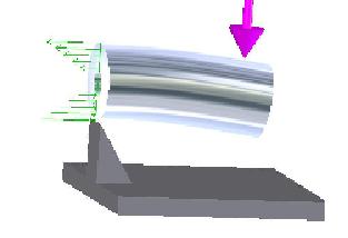
Figure 2-1: Tensile Loading Rotating Bending Fatigue (RBF) TestingRBF is an example of fully-reversing load which is when a specimen is put under tensile stress then released, then its put under compressive stress of the same value and then released. RBF can be visualized as a shaft in a fixed position but subjected to an applied bending load (Figure 2-2). The outermost fibers on the shaft surface on the convex side of the deflection will be loaded in tension (upper green arrows), and the fibers on the opposite side will be loaded in compression (lower green arrows). The shaft will rotate 180° with the loads remaining constant. The shaft stress level stays the same but the fibers which were loaded in compression will now be loaded in tension, and vice-versa.
Figure 2-2: Rotating Bending Image from www.epi-eng.com Current Test Methods and Existing Products
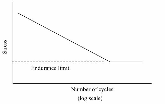
Fatigue test results are generally plotted into a S-N plot (Stress versus number of cycles to failure). A series of test are commenced by subjecting a specimen to the stress cycling. Starting at high stress amplitude the number of cycles to failure is counted. The procedure is repeated on other specimens at progressively decreasing stress amplitude. Data is then plotted into an S-N plot (example seen in Figure 2-3).
Figure 2-3: S-N plot
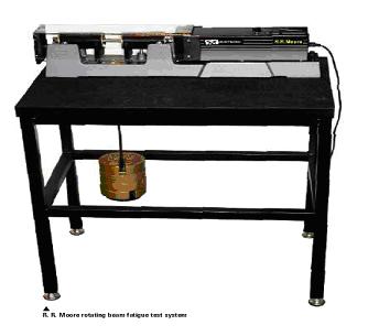
Cummins currently use Rotating Bending Fatigue test, to establish bending fatigue data. Tests are performed on machines that are similar to the Instron RRM-A1 (Figure 2-4). The specimens are tapered on the ends to match the tapers within the spindles of the machine, which are threaded to be held in place. The machine operates by applying stress through a direct application of weight to the specimen while it is in rotation. This gives the device an accurate and easy way to measure the bending load. The image bellow shows the Inston RRM-A1.
Figure 2-4: Instron RRM-A1 Image from www.instron.com Cummins uses the staircase method of analysis to generate their fatigue data. The method is efficient because test results concentrate mainly on three stress levels, which are centered on the mean stress level. Some disadvantages to this method are: only one specimen may be tested at a time, also it is a bad method for estimating small or large percentage points unless there is normal distribution.
Staircase Procedure:
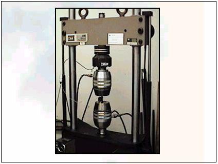
The MTS Servohydraulic Machine (Figure 2-5) is used for tensile testing. The machine can be used for both high and low cycle fatigue testing. Hydraulic actuators are used to apply a continuous axial load. This tensile fatigue tester subjects the specimen to a uniform stress or strain through its cross section.
Figure 2-5: MTS Servohydraulic Machine Image from www.coiledtubingutulsa.org
|
|
|