 |
||
 |
|
Pressure Vessel An alloy of steel should be used for
numerous reasons. First, the ability of
steel to avoid fatigue failure means that the device can be used much more
often without fear of a rupture when compared to a material such as
aluminum. Second, there are numerous
reliable and cheap surface treatments that can be used on steel. A surface treatment such as Chromium plating
would be favorable for the inside of the vessel to avoid possible oxidation or
other contamination of the fuel.
Finally, steel is readily available and is easily machined using standard
processes.
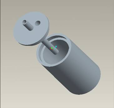
The finalized design of the pressure
vessel consists of two main parts, the body and the lid. The body can be made through welding a round
plate with an outside diameter of 16 cm and a thickness of 2 cm onto a 24 cm
length of steel pipe with an outer diameter of 16 cm and an inner diameter of
12 cm. The non-welded end should be
inset such that it has a 2 cm long, 1 cm deep lip. This lip should be tapped to accept the
matching threads to be placed on the lid.
Having a well machined threading fitting here helps seal the joint between
the body and the lid so that a gaseous or fluid leak becomes unlikely. A second seal can be accomplished by cutting
a shallow ring into the non-threaded surfaces where the body and the lid meet. Rubber o-rings can be fitted into these cuts
such that when the lid is tightened down a leak proof seal is obtained. These o-rings should have half of their body
sitting above the upper part of the cut when installed into the cuts. A drilled and tapped hole should be placed on
the welded end of the body in a manner which allows an air line quick connect
(such as a Coilhose Pneumatics
Male-Threaded Six-Ball Coupler (A937B4M)).
This quick connect will allow a standard male fitting to inserted in
order to fill the tank with the required pressure of Nitrogen. When not being used for this purpose the line
can be disconnected and the quick connect will provide a leak proof seal for
both the Nitrogen and alternatively the JP-10.
The lid of the pressure vessel can
be simply milled out of a 16 cm diameter round piece of 3 cm thick steel. A cut 1 cm deep and 2 cm wide from the bottom
edge is to be made along the bottom edge of the circle to match the similar
notch in the body of the pressure vessel.
Threads corresponding to the tapped section of the body are also to be
cut into this notched region. At the
center of the lid is a through hole that is drilled and tapped to accept ½” NPT
piping and threads. This hole is to be
used to run the piping system through which the JP-10 will be pressurized and
will flow through when the valve is opened.
Also through the lid should be a drilled and tapped hole that will accept the same type of air
line quick connect as is present at the bottom of the body of the pressure
vessel. This second quick connect
becomes important when the orientation of the pressure vessel needs to be
flipped.
Pressure Vessel Sketch: (all units in cm) Black represent the body of the pressure vessel, red lines
outline the lid, blue outline the piping, and yellow lines represent quick
connect air line fittings. Versatility
is a key aspect to the success of this design, and the pressure vessel’s design
reflects this. There are three main
orientations in which the design can be used during experimentation. The fuel delivery system may be set up such
that it sprays the fuel downward, sideways, or straight up. Any one of these orientations may be used by
the Air Force staff, while the design team would recommend that the downward
and upward shots may provide the best results.
This is due to gravity’s influence on the spray pattern. When shot upwards, spray droplets will
eventually run out of momentum and stall in the air, allowing for a greater
spread of fuel throughout the test chamber.
Likewise, a downward spray will allow for lower pressures to be used,
resulting in larger droplets that fall like rain drops through the test cell. In order to be able to facilitate these
three orientations the pressure vessel has two main design aspects. First, the air line quick connects on both
the top and bottom of the vessel (with the lid securely tightened down) means
that either the top or the bottom can receive the pressurized Nitrogen. This is important since the pressure vessel
can be flipped up to 180° in order to change from a downward to an upward
spray. Having the quick connects on both
sides also keeps one from putting the Nitrogen up through the fuel which could
cause the aeration of some JP-10 particles or the stagnation of Nitrogen
bubbles into the JP-10. The second important design aspect is the
threaded center hole in the lid of the pressure vessel. This allows for piping to be inserted from
both ends of the hole. Coming out of the
hold through the top of the lid would be a permanent pipe which leads to the
control valve and then to the nozzle. If
the experiment calls for a downward or a sideways spray then this will not be
changed with the lid being on the bottom of the pressure vessel pointing
towards the ground. For these spray
orientations the quick connect mounted in the body of the pressure vessel would
be used to fill the vessel with pressurized Nitrogen. Should the experiment call for an upward shot
a pipe with a length of 18 cm can be threaded into the bottom of the lid. When pressurized the JP-10 will flow up
through this pipe, through the permanent pipe and then through the valve to the
nozzle. In this scenario the quick
connect in the lid of the pressure vessel will be utilized for Nitrogen pressurization. For a sideways spray a 90° elbow will be used
to direct the spray parallel to the ground.
Placing this 90° elbow immediately before the valve should produce results
that would most closely relate to those of the same parameters that lack the
elbow.
3-D Rendering, Set Up For : An (1) upward spray (2) downward or sideways shot (3) Different angle for an upward shot
|
|
||||||||||||||||||
 |
||||||||||||||||||||
| © Copyright 2006-2007 FSU-FAMU COE. All Rights Reserved. | Design by Interspire |