|
Extrusion Block-Manufacturing |
|
The following section discusses the process used in manufacturing the extrusion block and problems encountered.
Process
The housing and the insert of the extrusion are made of two different materials. The insert is needed to withstand a large impact without changing the shape of the impact area. In order to do so, tool steel was machined down and hardened based on a recipe that was supplied by the customer. The tool steel that was used was D2 Tool Steel because it was supplied by the sponsor. The steel housing should be able to absorb the kinetic energy from the impact. Hot rolled steel was found locally for a very inexpensive price which fulfilled our requirements.
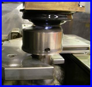
Extrusion Insert on Wire EDM machine
For the machining of both of these parts, the FSU Physics Machine Shop did all of the work to produce them. The insert was machined on a lathe, but first it was outfitted with dowel pins and cut in half. Then the part was turned down to size and shouldered. The conical section in the part was created with a Wire EDM machine . The conical section narrows down to such a small diameter, the wire EDM is one of the only ways to create the part. The first time, the part was machined completely then heat treated to increase the hardness. The other two variations were completed except for the conical section then subjected to heat treatment and followed by Wire EDM work.
The housing was done all on a milling machine. The part was made square and the appropriate holes were drilled. The first insert was heat treated so the section of the housing that held the insert was measured to fit exactly. This was done in order to prevent any variations that may have been developed from heat treatment. The parts were then dry fit together to ensure the compatibility.
Problems
Many of the problems the team encountered were due to lack of funds. The money given to the team was not available until mid to late March 07 and therefore, many of the tasks the team performed were done more creatively. The local support of machine shops for labor and donated materials helped the team have any product at all. This issue needs to be brought into light when looking at the project.
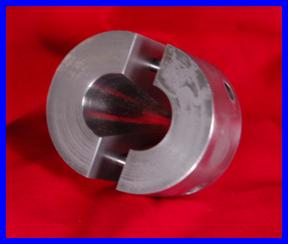
The design of the extrusion block had changed a bit in order to accommodate some of the knowledge that was obtained from machinist during the manufacturing process. The first major change was change of the insert to a circular cross section . Both parts were affected greatly by the change and made both parts much better. With a circular cross section that is stepped down to a smaller diameter, the housing block does not have the square cuts to accommodate the square shouldered insert and the insert can now be made from round stock. This greatly increased the machinability of the part and simplified the design.
Insert With Circular Cross Section
The second major change was the loss of the slit on the front side of the housing. This front slit was initially there to allow the block to be placed close to the lasers. This feature was removed for two reasons. The now circular insert would now need to be machined by drilling into the front of the block. A level surface is more desirable for drilling. If left with the channel, a circular part would be cut from it making the channel to look similar to a plane propeller. The sponsor also expressed the dislike of the feature and explained it wasn’t truly needed. When finding the material, steel was found locally and inexpensively that would not accommodate the channel. It was then removed.
The third major change was the placement of the holes on the housing. The holes were changed from the corners to the midline of the part. The previous design would take up a lot of room close to the edges for the block and the table, while weakening the section by adding more points of stress concentration.
|


|
Copyright 2006-2007 Famu-Fsu College of Engineering . All Rights Reserved |