|
Soft Catch-Manufacturing |
|
The following section will explore the methods used to create the soft catch used for the Dynamic Tensile Test.
Process
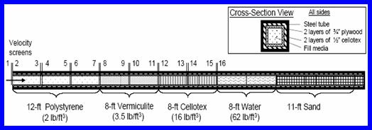
The soft catch design was largely modeled after the one used in “Soft Recovery of Explosively Formed Penetrators”. The diagram given in the paper was of a square channel, lined with wood, with the recovery medium within the center (Shown below). The team saw no need to redesign the experimental setup of the soft catch but rather manipulate the design to be on a smaller scale and more test-friendly. This part was made of a hollow square channel of aluminum that measured 4” in cross section. The top of the square channel was cut from the rest leaving a U-channel and a flat plate. The flat plate was cut into three sections to produce three separate lids for the part. The hinges were made from similar material. Two sets of aluminum rods were used, one of a larger diameter and the other smaller. The larger rods had holes drilled into them the same diameter as the smaller rods. The smaller rods slipped into the larger aluminum rods, then the larger rods were welded to the box. This created the hinges for the lids.
Soft Catch Diagram
A thick plate of aluminum was welded onto the back side of the channel in order to cap of one end. The front side was outfitted with a funnel shape in order to direct any misfired particle into the soft catch. Lastly, I-beams were cut down and used as stands to lift the entire soft catch of the table.
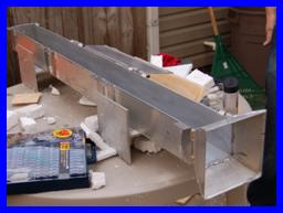
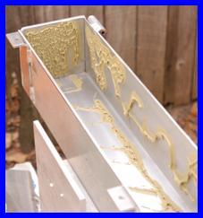
Soft catch metal work finished (Left) and adhesive application (Right)
After the metal fabrication was over, wood working was required. The idea behind the wood within the box was that if the particle strays from a flight path that is parallel to the walls, it would encounter the wood (a high density material) and travel back towards the low density material. The wood was cut from a sheet of ½” plywood. The sides were cut and a 45 degree angle in order to ensure their tight fit. Notches were made on the side pieces at the same location as the seams of the lids to establish placement of the dividers. The dividers would allow different materials to be separated so that each material could be removed separately for inspection and recovery. All of the wood was glued into the box using a product known as Liquid Nail.
Problems
As with most of the other components, the team experienced many money issues when this component was produced. The materials used for this component were chosen because they where given to the team without any cost. Without the generous contribution of others, the team would have nothing to report on.
The scalability of the design was an issue that was discussed with the sponsor. The cross section to projectile ratio is over 12 so the translation in the plane normal to the flight path should not be an issue. The problem comes into play with the length of the soft catch. The data and equations are all empirically interrelated. The ballistics data is dependent on so many variables (cross section, density, soft catch material, velocity, Cd dependence on velocity, and cross over region) that test needs to be done with the actual projectile in order to develop a soft catch of correct length. This became a problem during design and still plagues the team. The model manufactured was used to begin collecting data and to determine what materials would be relevant and what lengths the projectile would need to slow down without deformation. |


|
Copyright 2006-2007 Famu-Fsu College of Engineering . All Rights Reserved |