|
Test Integration– Integration at Eglin |
|
This section involves the integration at Eglin Air Force Base.
Integration at Eglin
After all of the components of the objectives were designed and manufactured, they were taken to Eglin Air Force Base to be used for the first time as a conversion from the Taylor Test to Dr. Gray’s Test. Parts of the Taylor Test not needed were disassembled and new components were assembled in their place and aligned with the camera and lasers.
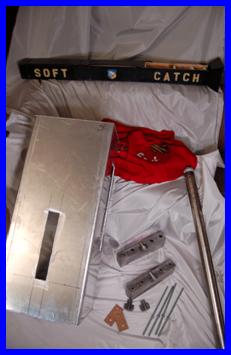
All Components of Dynamic Tensile Test
Breakdown of Taylor Test
The Taylor Test has an eight inch diameter cylinder (anvil) that they shoot smaller cylinders into. A cradle is bolted to the table that allows the anvil to sit securely in it while preventing the anvil from moving when struck by the cylindrical specimen. The faces of anvil are finely polished surfaces so the anvil should be removed with care not to scratch the surfaces. Once removed, the nuts, washers and all thread rods can be removed to free the cradle from the table. The hardware for the cradle is assembled back onto cradle after it is separated from the table. The shield and anvil in the Taylor Test were removed prior to arrival. The cradle was removed from the table as said.
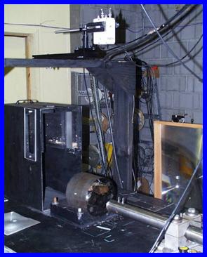
Taylor Test Set-Up at Eglin
Installation of Dynamic Tensile Components
One of the most crucial interfaces is that of the alignment of the gun tube barrel axis with the entrance/exit axis of the extrusion device. The center of the soft catch entrance should be aligned on that same axis as well. The camera and laser view sites should not be obstructed by the Safety Shield and the sabot should fit snug into the barrel of the gun tube.
The spherical specimens were provided by Eglin; however the sabots were machined with in the group. After integrating the two components, the sphere fit nicely into the sabot and the payload package fit snug into the gun tube barrel.
The breech of the gun tube was removed and a laser was shone done the barrel. That laser was used to align the extrusion device and soft catch with the barrel. The extrusion device was put on a one eighth inch thick cork and rubber gasket so tightening the bolts on the block compresses the gasket and acts to fine tune the height of the Extrusion device. This aspect of the design was flawless.
From the first Eglin visit, it was anticipated that either the lasers or the camera would need to be adjusted once the tests were converted from one to the other. As we anticipated, if the extrusion device is aligned with the camera than the lasers must be moved, and vise versa. After inspection of the design space with the manufactured components this was verified.
The Safety Shield was functional in the design space and satisfied its objective. The cuts in the sides of the shield fit nicely around the openings of the soft catch and gun tube. After inspection, any changes to the laser or camera configuration to properly align the new experiment will not affect the functionality of the Safety Shield.
|


|
Copyright 2006-2007 Famu-Fsu College of Engineering . All Rights Reserved |