|
Extrusion Device-Design 3&4 |
|
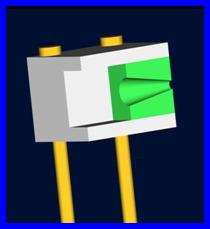
Design 1 and 2 were shown to the Air Force sponsor upon his visit to the college. He stated that the designs needed to follow Dr. Gray’s test hardware more closely and that the extruding channel would need to be removed. The channel obscures the point of interest which is the extrusion of the material and the photography needs to capture this process. This led to the development of Designs 3 and 4 (Appendix K). Design 3 incorporates the inserts used in the previous design. The inserts are removable and can be repaired and replaced when necessary. The significant change in this design is that the test hardware is now modeled after the conical cross section seen in Dr. Gray’s simulation. The design also features a recessed segment before the insert to limit the reaction of the sabot when it impacts with the outer block. The larger diameter on the insert is small enough for the sphere to enter but larger than the diameter of the sabot. This will cause the sabot to deflect off the outer face and preventing it from interfering with the extrusion. The insert is again held in by square shoulders. The only difference between Design 3 and 4 is the housing block. Design 3 features clamshell housing while Design 4 incorporates a one piece design. Design 4 was an attempt to limit the number of parts in the test segment in order to make it easier to use. Both Design 3 and 4 are represented in Figure 8. Design 3 has a seam along the horizontal mid-plane of the housing block while Design 4 would not. The inserts in both designs separate.
Design 3
Pros: The extrusion section is removable. The extrusion section is conical. The casing uses a clamshell design for ease of remove inserts, and the extrusion process is visible. The pocket in the design provides containment for the sabot during deflection on the front face. The cost is optimized by the use of a limited amount of high strength steel. Cons: This design contains the largest number of parts and would involve the most machining.
Design 4
Pros: There would be fewer parts to be machined and stronger along the seam in Design 3. The sabot would be contained, the extrusion section is conical, and the cost is reduced by having the smallest amount of high strength material. Cons: The test section could be harder to remove especially after a test while the energy of the impact could cause the device to expand thermally and cause extra stress within.
Design 3 and 4- Half view cut along the middle line
|


|
Copyright 2006-2007 Famu-Fsu College of Engineering . All Rights Reserved |