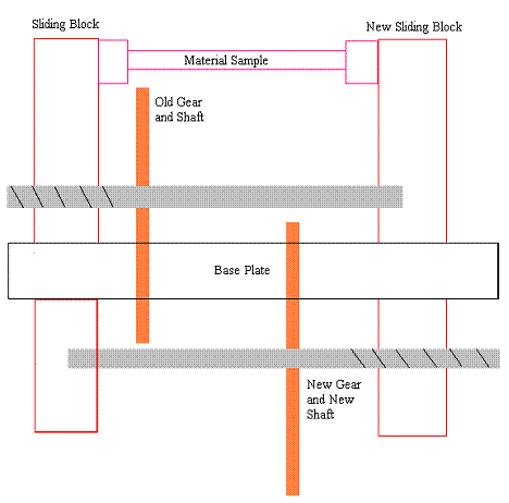
Design number two, pictured in Figure 5.2, is taking the sliding part of the old machine and mirroring it. The group came up with the idea of adding another motor that will control the movement of the previously stationary block, making it a new sliding block. The original design used one motor that made one block that was attached to the sample move one way, while the other end of the sample was anchored to a block that stayed still. This made it impossible for the machine to exert both tension and compression on the material sample because the sliding block could only move in one direction. If an additional motor is to be added and connected to an additional gear, this new gear will allow the previously anchored block to become a new sliding block. Since both blocks will now have the ability to move, the person controlling the machine will be able to make the blocks, with the material sample securely connected between, move in opposite directions of one another. This will allow both tension and compression to be applied to the sample, accomplishing one of the goals. A major problem with this design is its complexity. This will be a very hard design to implement because it almost doubles the amount of moving parts. Also, this design will require major changes to the original machine, just like the first design idea, for it to fit on the base plate. Another major problem with this design is its size. The addition of a new motor, gear, shaft, and gear housing will take up a tremendous amount of space. Since size is a major constraint on this project, these new parts may just take up too much space. Again, the implementation of this design idea will require the group to overcome many tough problems, but it is possible.


