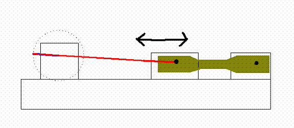
With design number one, the group was trying to implement design ideas that were learned in previous classes. Slider and rocker mechanical designs are two examples of the types of mechanical systems that have been taught in previous classes. Design number one, shown in Figure 5.1, implements a typical slider mechanical design. This design consists of a motor that sits raised above the base plate of the machine. This motor will rotate a small arm, which must be at least five millimeters in length, which is connected to a longer arm that is connected to a slider block. This slider block will be able to slide along a track on the base. The purpose of the track is to keep the slider block moving in a straight line. Securely connected to this slider block will be the sample that is being tested. The other end of the sample will be attached to a block that will remain stationary on the base, connected by at least four bolts. As the motor rotates the small arm in a full circle the sample will be subjected to alternating tension and compression, which is one of the goals. One major problem with this design is the fact that the motor will be in the magnet along with the machine. In the original machine, the motor was located at the top of the machine, outside of the magnet. This protected the motor from the magnetic field and the extreme cold. With this new design, the motor must be able to withstand the 20-Tesla magnetic field and temperature of 4.2 Kelvin that are found inside the magnet. Any motor that can run in that volatile of an environment will be specialized and very expensive. Another problem with this design is the group would have to vastly change the design of the upper part of the old machine to make room for this design to fit on the base plate. This would fail one of the goals because major changes to the old design would have to be made. Overall this design is a good idea and uses some very creative thought, but difficulties would have to be overcome to implement it.


