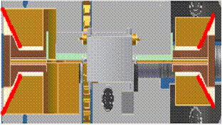
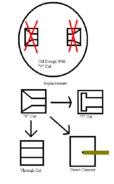
This idea is by far the group’s favorite design choice. It is the simplest, and while still needing a lot of work, it will require the least amount of change to the original design. Design number three centers around the “V” cut that is present on both the sliding and stationary blocks on the original machine. The purpose of this “V” cut, in the words of Dr. Han, is to “pull the sample in one direction with tensile stress and align the sample”. Figure 5.3 shows a very clear illustration of the “V” cut. This is a very important aspect of the old machine, but it is also the reason the old machine can only put a tensile force on the material sample. This is because the “V” cut only guides the sample holders. It is in no way connected to the sample holders, it only pushes against them because they are the same shape. Design three entails getting rid of the “V” cut completely and designing a stationary and sliding block that can connect to the sample holders instead of just guiding them. Design three will also require the group to completely change the material sample holders, making it possible for them to connect to the blocks. This design idea sounds simple, but there are still some complications and problems associated with it. The first problem will be obtaining a motor that has the capability of operating in both forward and reverse. Since this design uses the idea of only having one sliding block, that block will have to move in both directions in order to place both a tensile and compressive force on the material sample being tested. Purchasing an electric motor like this could get expensive, but the Magnetic Lab might have a motor that will suit the group’s needs. Another potential problem with design three is the fact that the sample holders will now be connected to the sliding and stationary blocks. This additional mass, plus the addition of a tensile and compression force may be too much for the blocks and they may physically fail. Extensive stress tests will have to be done to ensure that the new design will be safe and the additions will not increase the potential for failure. An engineering drawing for design three is shown in Figure 5.4. This drawing shows some possible replacements the group generated for the “V” cut. The first replacement is called the “T” cut. The theory behind this idea is a “T” shaped sample holder could fit directly into the blocks, and because the block supports the holder on both the front and the back, tension and compression can be accommodated. The second idea is a through cut. For this replacement the group could use the “T” shaped sample holder again, but instead of the block supporting the holder, bolts will support it. This cut makes it easy to bolt the holder to the block. The third idea is a “direct connect”. The group came up with an idea to directly connect the sample to the blocks, negating the need for a sample holder. This will simplify the process and make the design cheaper if it is possible. If design three is chosen the group will have to consult Dr. Han and use three dimensional programs to determine which replacement for the “V” cut would work the best.


