Note: These processes are
described in detail with photographs and drawings in the instruction
manual.
The
male mold form was provided by the sponsor. This was created in a rapid
prototyping machine and coated with epoxy to seal it. In many cases in
industry, mold forms and molds are machined from metals or polymers. Though the group has access to a five-axis
Computer Numerical Controlled (CNC) mill at the composites lab, there are a
few downsides to machining and using these materials. These materials are very expensive. For example, a bar of aluminum 2.25’’
square and 36’’ long to make this form would cost the group $170.75
(Speedy Metals). Also the group has to wait weeks for these materials
to ship. If a machining
error occurred, the loss would be great. This led the group to make molds out of gypsum plaster,
which is far less expensive and more readily available. The mold box was made from particle board
5’ x 10’ sheets 3/4” thick. This was used
because of its availability, consistency, and workability.
All
of the wood was sprayed with Minwax Polycrylic polyurethane. This was used because it provides a
smooth, durable finish, with less than one hour recoat times and simple
water cleanup. The coating was
sprayed with an automotive style spray gun for optimum volume and coverage
control. Also, the
coating is much more affordable to purchase in bulk than in individual
spray cans. The box was assembled
using #8 X 1” sheet metal screws throughout and labeled to ensure proper
and easy assembly and disassembly.
After disassembly, each piece was waxed with paste
wax. This wax, commonly used on furniture, was used to seal and level any
small imperfections as well as ensure proper release of plaster castings. With
a center line drawn on the mold form, the mold form and box were
assembled. The bottom half of the
mold was poured and allowed to cure.
After leveling a waxing the bottom of the mold, the top half was
poured. After careful separation of
the molds, the corners were rounded with sandpaper. The molds were cured in
the oven for 24 hours and then wax was applied to the warm molds.
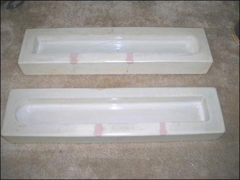
Figure 7.1: Molds
The
plaster mold was coated thoroughly with paste wax to keep resin from
leaching into it. The wax was
allowed to dry for five minutes between coats and was buffed lightly after
the final coat. The area of the mold
where the cloth is laid was coated with Poly Vinyl Alcohol (PVA), a water
based release agent. The PVA was allowed
to dry for 15 minutes. The first
layer of carbon fiber was laid and formed into the mold. The excess was then trimmed. The mold was sprayed with a common spray
adhesive to hold the cloth in place.
This step does not bond the cloth to the mold. It temporarily bonds the cloth to the
layer of PVA release agent.
Subsequent layers of the cloth were trimmed and bonded to previous
layers. A layer of peel ply was placed
on top of the final layer of cloth.
This material keeps the flow media and vacuum bag from being bonded
to the carbon fiber. A layer of mesh
flow media was placed over the peel ply.
This media allows the resin to flow quickly and evenly into the
cloth. If the peel ply is not
positioned correctly, the flow media will permanently bond to the carbon
fiber thus ruining the part.
The
part was covered in a polymer sheet that is sealed with vacuum bagging
tape. Inlet and outlet tubes were
sealed into the bags. The ends of
the tubes were covered with a small piece of flow media to keep the bag
from stopping the flow. The inlet
tube was crimped with locking pliers.
The outlet tube was connected to a vacuum chamber. The vacuum chamber was connected to a
vacuum pump. This chamber is used in
case any resin flows into the vacuum hose.
Cured resin is easily cleaned from a vacuum chamber. A small amount of resin would ruin a
vacuum pump that easily costs thousands of dollars. Once proper vacuum is established, resin was
allowed to enter the inlet and infuse the part. When the part is completely infused, the
inlet and outlet are closed. The part was allowed to cure for 18
hours. The part was then removed
from the mold. The part was trimmed
with a diamond blade saw and the edges were sanded. The cap parts and
bonding strips were cut from a flat sheet of infused carbon fiber using the
water jet machine. Also the top
opening and vent in the fuselage pieces were cut using the water jet. The parts were lightly sanded, and the
fuselage was bonded together. The
completed fuselage was coated lightly with Minwax
Polycrylic to seal and protect the shell.
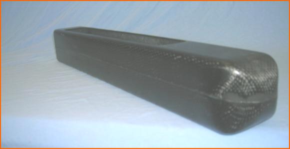
Figure 7.2: Fuselage (Iso)
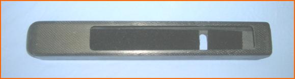
Figure 7.3: Fuselage (Top)
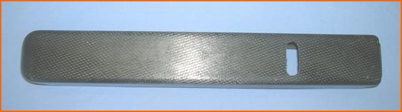
Figure 7.4: Fuselage (Bottom)
Motor Mount Plate
In order to cut the motor mount plate, the aluminum was
secured in the water jet machine. The
drawing exchange file was loaded and the part was cut. The part was painted black to promote
military tactical advantage and was then bonded to the fuselage.
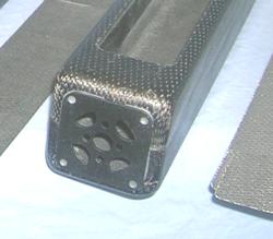
Figure 7.5: Motor Plate