|
fvc |


|
Florida Department of Health - Florida State University |
|
Group 2 - Radon Mitigation |
|
Design |
|
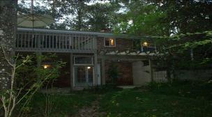
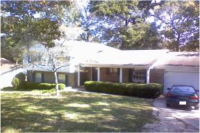
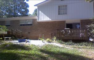
After going in the community Group 2 was able to find two candidate houses. One candidate allowed us to install a mitigation system the other at the time did not have the financial means to allow us to install a system. For them, Group 2 design a system specific to their home. Candidate House 1: This house was built in 1961 and the current owner has lived there since 2000. This is a two story slab home that can be seen in Figure 1 and Figure 2 with an air conditioned square footage of 1586. This home sits on a lot that measures 115feet by 170feet, the lot does slope from front to rear as seen in Figure 25 and Figure 26, as the front of the house is the second story and only seen from the front, where in the rear of the house exposes the first floor of the home. |


|
After careful analysis a depressurization system was chosen to be installed on Candidate House1. A depressurization system creates a low pressure field under the house in order to the radon to be drawn to the path of least resistance, this is done by drilling a hole into the slab of the home, digging five gallons of soil from the underneath the home, and installing an air tight ventilation piping system that is attached to a fan in the attic. The fan will then vent the radon though a vent in the roof. Mitigation System Design:
|
|
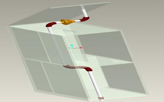
The base of the systems starts at point 1, this is the point at which will sit below the slab of the home pulling the radon away from the soil. The pipe is shorter than the stock 10 feet in order to allow easy positioning. Point 2 is a coupling that is still in the basement and attaches to the pipe that will be brought to the second story of the home. Point 3 is the 10 foot pipe that is brought up from Utility Closet 1 and brought into the Bathroom Closet on the second story. Point 4 is another couple to connect the pipe that will be brought in to the attic. Point 5 is the piping that will be brought to the outside of the home. Point 13 is the exhaust pipe that is outside the from the mitigation fan in the attic to a point on top of the roof. Candidate House 2: This home was built in 1974 and the current residents have lived there since 2002. Candidate House II is a split three story multi-slab home with 2325 air conditioned square feet. The main entrance is located on the first story of the home as well as the kitchen, dinning room, and living room. The family room is located in the basement |
|
Mitigation System Design: |
|
The system starts on the ground underneath the crawl space at point 1. Point 1 shows two 4 feet long pipe that are brought into point 2 which is a tee couple. The tee couple is connected to a 30 inch pipe that is brought into the mitigation fan at point 3. The mitigation fan is connected to another 15 inch pipe that is connected to a 90 coupling at point 4. Point 4 will come within inches of the wooden floor joist of the above living room which with allow the 17.5 foot section of pipe to be mounted and secured. Point 5 is the 10 foot section of pipe. Point 6 is a 90 deg coupling that will allow the system to come towards the outside of the house, underneath the deck. Point 7 connected to the 90 degree coupling is a 17.5 foot section of pipe made up of a 10 foot section coupled to a 7.5 foot section of pipe. Point 8 is a 90 degree couple fitting that directed the pipe down before the pipe reaches the edge of the deck. Point 9 is a 56 inch pipe that starts at the underside of the deck and ends buried in the soil at the edge of the deck. Point 10 is a 90 degree coupling that directs the piping out away from the house underground. Point 11 is a 10 foot section of pipe that is buried underground to hide its location. Point 12 is a 90 degree coupling that directs the piping above ground is connected to a 4 foot section of pipe that is brought above ground to vent the radon to the surrounding air. Point 12 is a cover that will prevent wild life from tampering with the system and rain from entering the system. |