 Rotational Compressor Valve
EML-Senior Design- Spring
2012
Team 18
Alejandro Castro
Sam Leuthold
Andrew Borger
Department of
Mechanical Engineering, Florida State University, Tallahassee FL
Project Sponsor


Project Advisor:
Dr. Van Sciver
Department of
Mechanical Engineering
Project
Scope
Problem Statement
Current gas compressor intake and exhaust valves restrict flow,
which cause inefficiencies within the system. The currently accepted valve is a
plate valve. The problem with these valves is that the gas must flow around the
plate rather than taking a more direct efficient path. This causes a
restriction of mass flow both coming in and out of the cylinder and the
addition of unwanted heat to the gas. A better flowing valve is needed. The
main proposed solution is a valve that rotates to allow for flow. A mode of
rotating the valve is needed.
Justification/Background
The project focuses on improving the valve design used in GE gas
compressors. These compressors are used all over the world to compress gases
for either transportation or storage. They are piston type units that operate
on a dual stroke cycle that uses the piston to compress gas on each forward and
backward stroke. Each side of the piston requires two sets of valves, one for
intake and one for exhaust.
Currently, GE compressors utilize a plate type valve for this
application. A plate valve is a valve that is activated by a pressure
difference that pushes against a specified spring force for the given
compressor. The pressure difference at which the valve opens can be changed
using different spring rates. As the pressure acts on the sprung plate, the
plate is pushed forward, opening the valve and allowing the fluid to pass
around the plate. While this design is relatively cost effective and is very
reliable, it does not flow very efficiently due to the fact that the fluid must
pass around the plate, which is not a very direct flow route.
In order to maximize efficiency of the compressor, it is important
that the valve design has as high flow as possible. During each stroke of the
piston, the valve creates a minor loss in the flow of fluid into the cylinder.
A restrictive valve limits the flow into the cylinder, which forces the
compressor to go through more cycles to pump the same amount of gas. A better
flowing design can be created using a more direct flow path that would increase
the overall efficiency of the pump by limiting the pumping losses of each
compressor cycle.
Objective
One objective is to find a means of operating, designing, and
producing a rotational compressor valve. This valve should be able to flow gas
into and out of a GE compressor more efficiently while being completely
leak-tight. The new valve design must be adaptable to current GE compressors
and should be cost effective. The new design must also be at least as reliable
as existing designs in order to limit compressor down time during maintenance.
Methodology
To begin deciding what aim we will be taking for the project we
will first analyze and understand the products that are already available. Once
we know what valves are currently being used in the field, we can research the
problems these valves currently posses.
It is also important that the gas compressor that the project is
focused is well understood. This is critical to designing the valve towards the
applications parameters. Some of these parameters are operating pressure, size
of the valve necessary to fit the seat, and operating temperatures.
Once the style of valves already available, their weaknesses, and
the compressor in which the valve will be fitted for are known, we must decided
in which manner we plan to have the valve operating. Each type of operation has
its pros and cons. Though some may have a more reliable operation short term,
they may not have long life times.
Along with the type of valve operation, we must analyze the amount
of flow rate achieved by the decided design. In this market, flow is money. The
more flow per valve opening, the better. The valve must also produce efficient
flow avoiding adding to much heat to the gas due to friction. With a few types
of operations decided on, a decision matrix will be implemented to assure that
the design decided on is indeed the best design overall. The proposed
rotational valve will be included in the matrix to decide of it is one of the
better choices.
After the mode of operation is known and the desired flow rate is
achieved, materials for the fabrication must be chosen. The materials for the
entire valve must be able to withstand long time exposure to natural gas.
Further more, the valve must be airtight. No amount of gas can seep around or
through the valve. So a type of seal must be implemented in which can also last
the life of valve itself.
With the style of valve, the desired flow rate achieved, and
necessary materials are chosen, a pro-type must be produced. To do this, we
will use a 3-D modeling program such as ProE to produce a digital model of the
valve. With the digital model complete, we can then produce the physical part
itself. Most of the parts will be sent to the on campus machine shop to be
fabricated. Any part that is too intricate to be fabricated on campus will be
sent to GE to be made. Any parts such as springs and bolts will be purchased
for a local store of off the Internet.
Having the part produced then allows us to build a working
simulation. Along with group 19, whom are producing the digital instruments and
software to be able to analyze the system, a physical representation of the gas
compressor will be made. Both the sensors and valve will be modeled.
Product Specification
It is important that
the valve has a balance of cost, reliability, and performance. If the product
turns out to be more expensive than the existing valves, the pros must out
weigh the cons. The desired mode of operation of this valve is a rotational
manner. When the desired pressure of the gas cylinder is achieved, the valve
must rotate to allow the gas to flow out. When the pressure drops, the exhaust
valve must rotate shut as the intake valve rotates open. Then again, as the
pressure increases, the intake valve must rotate shut. This device should be
able to be used as both an intake and exhaust valve. The device should also be
able to be fitted onto all or most of the gas compressor out on the field today. This product should be able to be easily installed in
replace of the existing plate and poppets valves with no modification to the
compressor. The entire project should fall within the budget range of two thousand
dollars.
Costumer Needs
• Product must operate in a rotational manner
• Flow volume and efficiencies must out perform
current designs
• The valve’s cost must be justified by its
performance including efficiency, cost, and
lifetime
• The product must stay in the budget range of
$2000
• A working model is to be made at the end of
the design process
Expected Results
The valve should operate at a higher efficiency than the current
model and have a higher factor of safety. A rotating action will open the valve
as well as close it with a tight seal. This rotation may be actuated by an
electric motor or a mechanical system synchronized with the compressor. Our
design must be contain the complexities necessary for operation but still be
simple enough to ensure durability and ease of installation.
Constraints
A G.E high speed reciprocating gas compressor has specific
pressures and temperatures that it operates between. Exact dimensions of the
space where the valve fits will constrain the size and shape of the design. The
valve must be tested thoroughly to ensure that the design concept and material
selected can withstand the rigors of operation. The valve must be designed,
fabricated, and tested within the allotted time frame of 18 weeks and the
budget determined by G.E
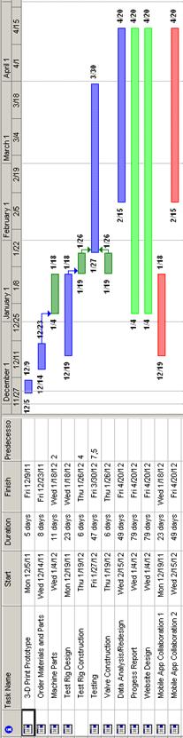
Project
Plan
To begin the
semester, the ordering of all the materials is to be completed. Once the
materials have been ordered, the design of the valve will be “touched up” and
finalized so the drawings and materials can be sent out for machining. As the
parts are being machined, a test rig will be designed and constructed. The rig
will be fitted with thermocouples, pitot-static tubes and pressure gauges to
collect data. Once the parts are machined, the construction of the valve will
take place. With both the rig and valve constructed, extensive testing will be
done. If time allows, the test results will be used to improve the original
design and create an improved final design prototype. Our group will be collaborating with group
19, Mobile Application for Android, to be able to compare results and join
designs. During the entire process, the website will be updated on a weekly
basis.