Vehicle Video
Performance Data
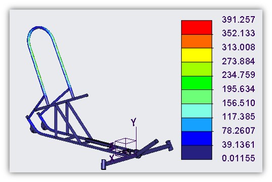
Top Load
The frame was tested in PTC Creo appling a 2670 Newton force at 12 degrees from vertical. Testing revealed that a max von Mises stress of approximately 391 Megapascals was observed.
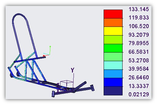
Side Load
The frame was tested in PTC Creo appling a 1330 Newton force at shoulder height on the frame. Testing revealed that a max von Mises stress of approximately 133 Megapascals was observed.
Performance Requirements
To be able to enter the ASME HPVC 2019, certain vehicle peformance parameters needed to be met. These include:
• Vehicle must be able to brake in 6-meters from a velocity of 25 km/hr.
• Vehicle must be able to complete an 8-meter radius turn.
• Vehicle must possess a Roll Protection System (RPS).
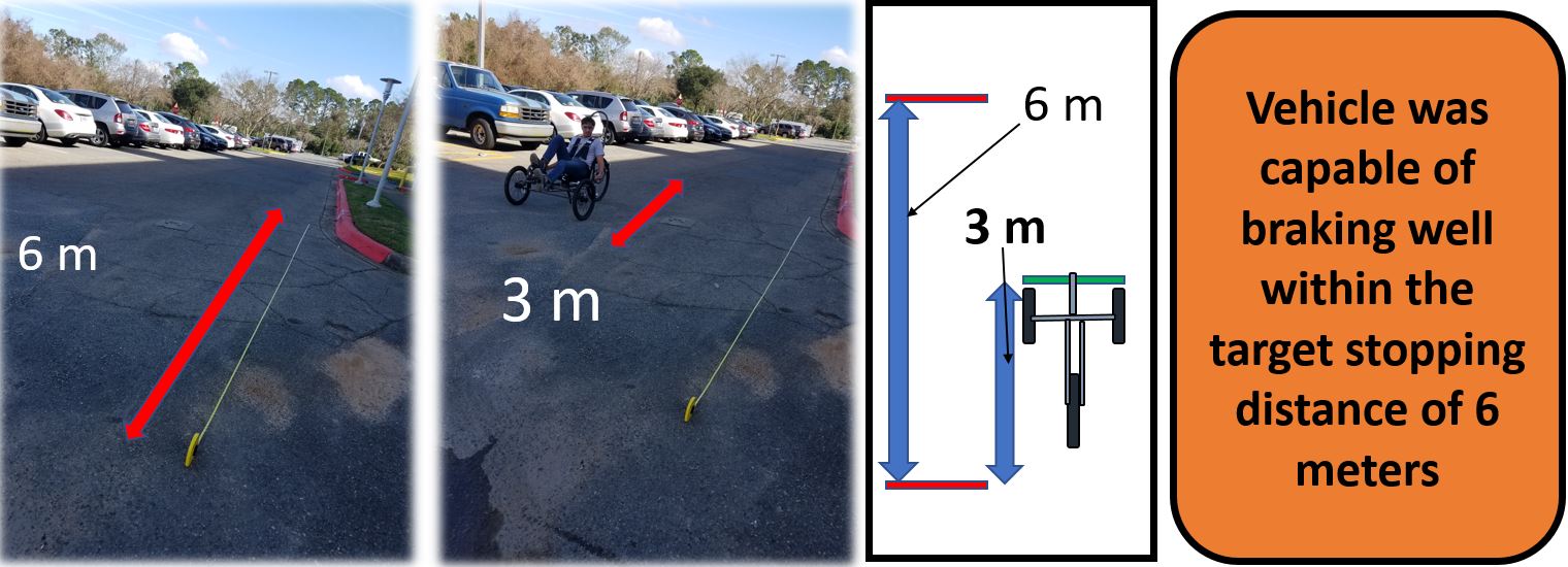
Braking Test
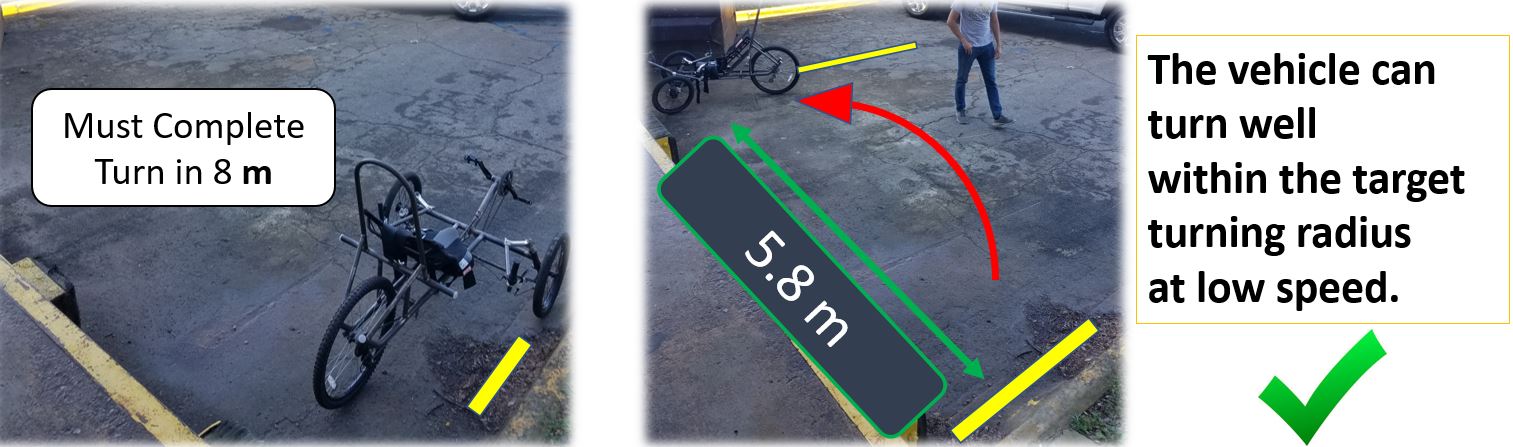
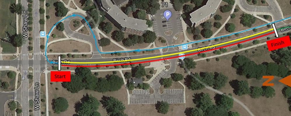
Turning Radius Test
Competition at the College of Engineering
Having met our objective of creating a vehicle capable of entering and competing in the ASME HPVC 2019, Team 512 elected to emulate the events of competition at the FSU-FAMU College of Engineering.
• Team 512 chose to recreate the ENDURANCE event in the COE's parking lot. The track stretches 1-kilometer and replicates the obstacle course present at competition. The ENDURANCE event consists of speed bumps, stop signs, hairpin turns, a slalom, a rumble strip, and a quick turn.
• Team 512 chose to recreate the SPEED event on a 270-meter straight and level stretch of road close to the COE.
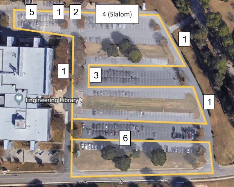
| Number | Obstacle |
|---|---|
| 1. | Speed Bump |
| 2. | Stop Sign |
| 3. | Hairpin Turn |
| 4. | Slalom |
| 5. | Rumble Strip (potholes) |
| 6. | Quick Turn |
Vehicle Specs
| Description | Unit |
|---|---|
| Material | Low Carbon Steel |
| Length | 2.13 m |
| Width | 1.08 m |
| Height | 1.29 m |
| Wheelbase | 1.07 m |
| Weight Distribution (Front) | 18.1 kg |
| Weight Distribution (Rear) | 13.6 kg |
| Total Weight | 31.7 kg |
| Wheel Size (Front) | 0.508 m |
| Wheel Size (Rear) | 0.660 m |
| Frontal area | 0.81 m2 |
| Steering | Front |
| Braking | Front |
| Estimated Coefficient of Drag | 0.8 |
| Maximum Competition Velocity | 27.36 km/hr |
Future Work
Testing and analysis completed, Team 512 assessed what improvements could have been made on T-Bone and for what reason. Addressing this information is detrimental to the understanding that as engineers, something more can always be done. This section highlights and proves these suggestions for future seniors of the FSU-FAMU COE that inherit this project.
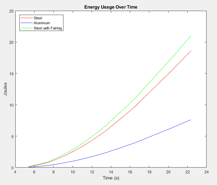
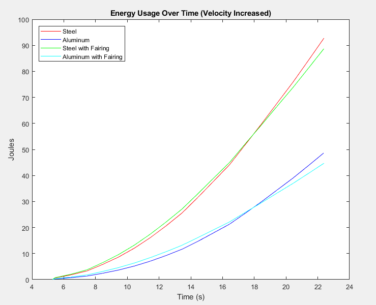
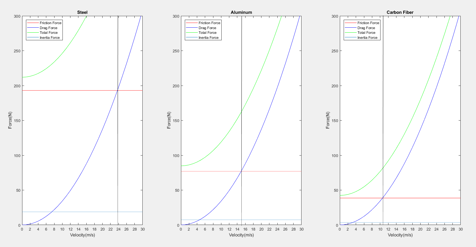
Energy Study