


Currently, there are no uniform Geometric Dimensioning and Tolerancing (GD&T) automated process for additive manufacturing in the aerospace industry. Some American Society for Testing and Materials (ASTM) standards do exist, however, they are specific towards metal powder bed fusion. The scope of this project is to design and develop a new process to quantify and decrease variability in 3D printed parts. To do so, the variability of various 3D printers will be also be quantified, with the end goal of developing a new automated GD&T system for 3D printed parts that will not only decrease variability, but reduce waste in processing time.
To further project progress, the industrial engineering department and mechanical engineering department have teamed up to provide engineers who work together to develop, manufacture and design the automated process at hand.
![]()

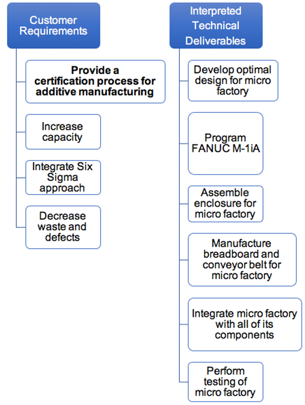
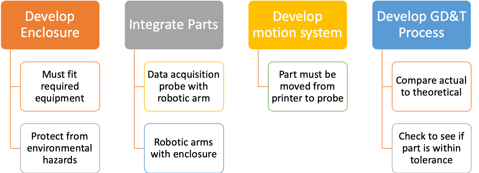
During the Define Phase, the team began by identifying the root problem and developing an initial scope. This initial scope was adjusted and narrowed down to quantify, and thus reduce, variability in 3D printed parts by examining the not only the part variability, but the variability of the printers themselves. We functionally decomposed the problem statement, interpreted customer needs, and established some base design goals for future phases.

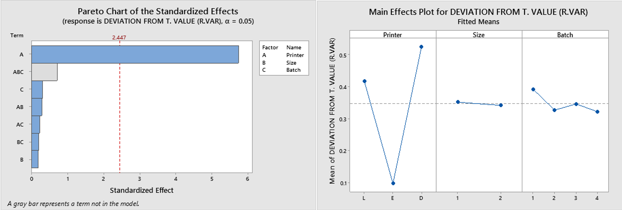
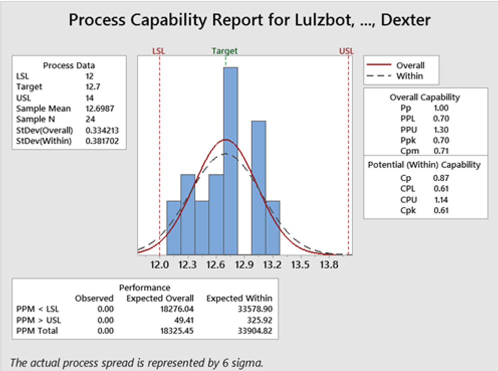
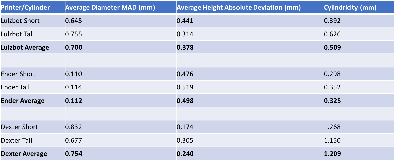
During the measure Phase, the team began by creating a test plan to determine the variability and errors of three 3D printers; the Lulzbot, the Dexter Arm, and the Ender. The team printed 20 cylinder, with varying diameters (0.5" and 1.0") and consistant height. From here, caliphers were used to measure each and determine statistical anomalies between printers. The various tools utilized in this phase were the DOE analysis and process capability charts.
Analyze Phase
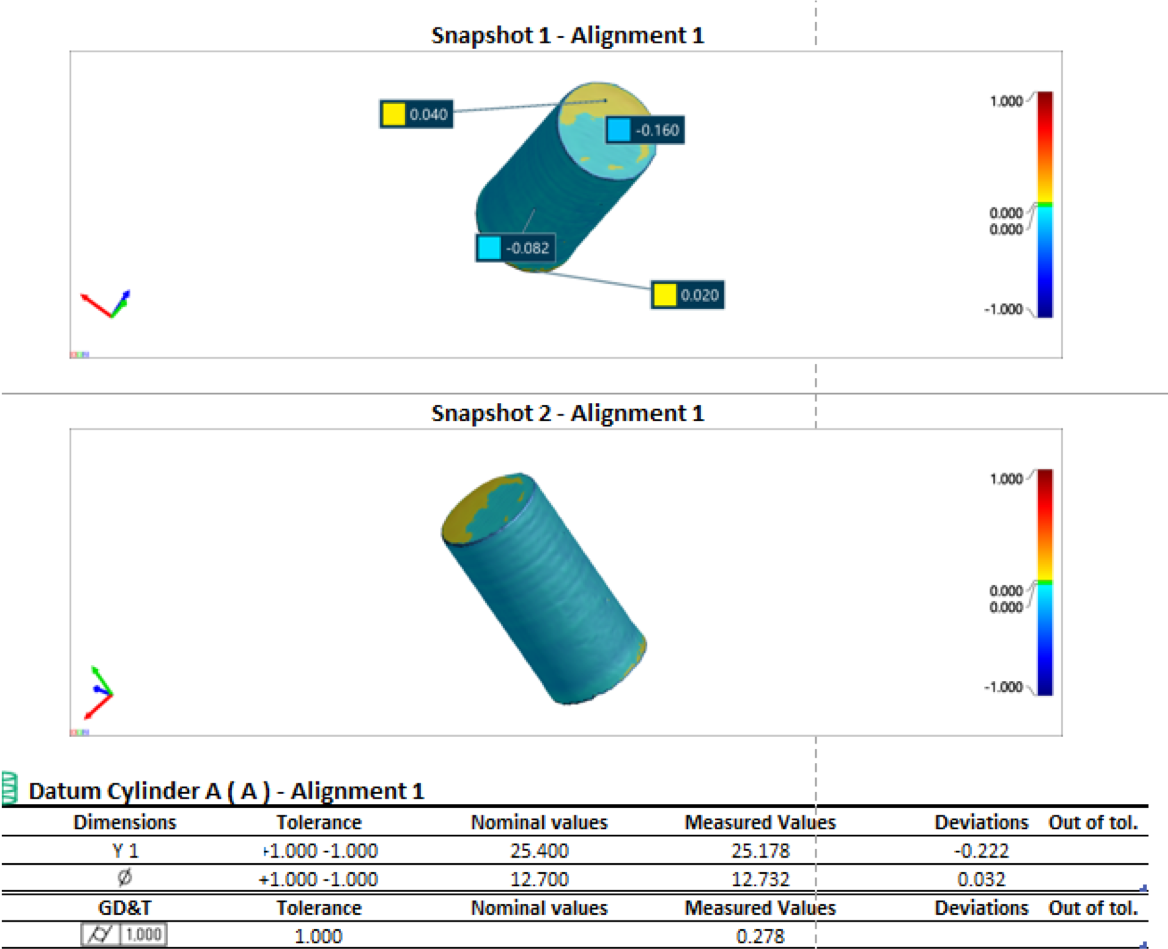
At the conclusion of the analyze phase, the team was able to use the VXinspect software to further analyze the cylinders and characterize/quantify our printer variability. This software allows for a 3D scan to be overlayed with a CAD model. It automatically creates a color map of the scan deviation from the CAD model. This led into the design phase, where various components were developed at the request of the team's sponsor.
Design Phase
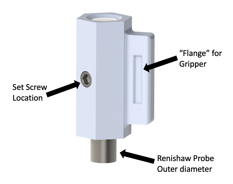
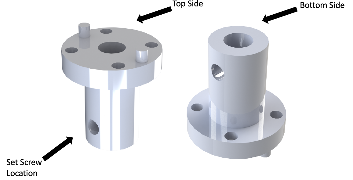
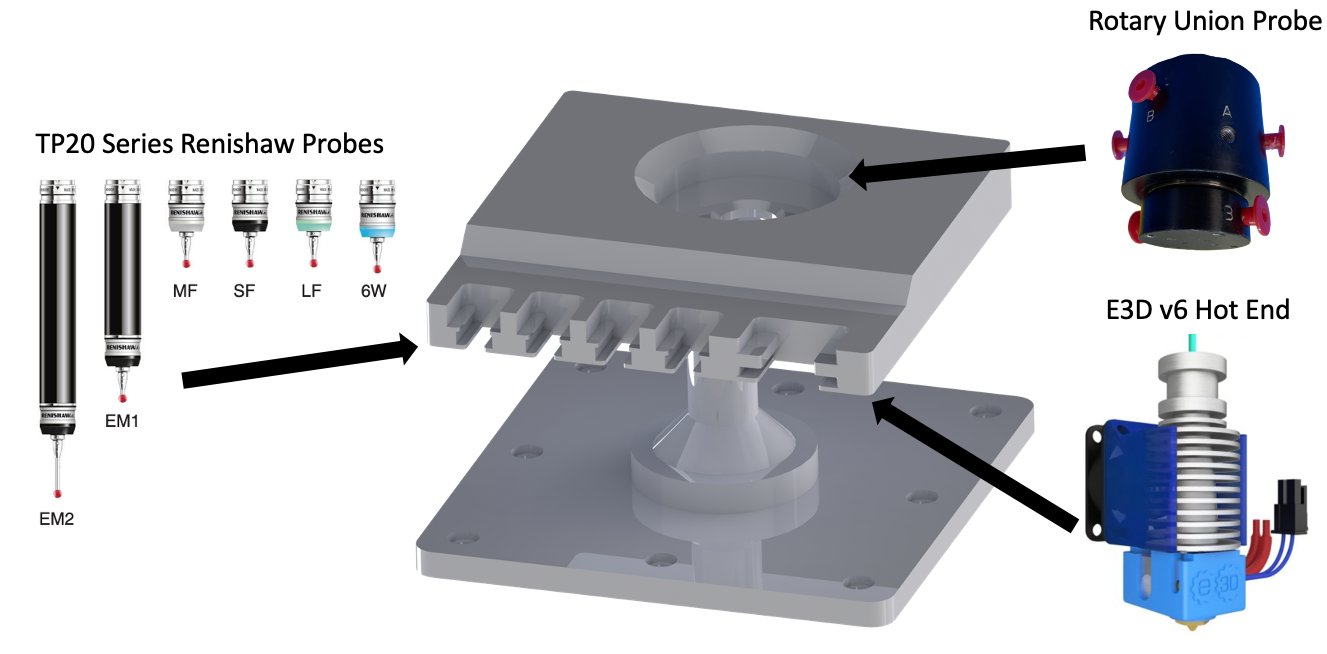
![]()