Sponsors and Advisors


Abstract
The purpose of the RE-RASSOR (Research and Education- Regolith Advanced Surface Systems Operations Robot) Project is to design an educational model of NASA’s RASSOR, introducing STEM concepts in middle and high schools. The RASSOR is a remote-controlled robot used on the moon to lift and transport large loads of rocky material in low gravity. The RE-RASSOR Shoulder Project focuses on creating a smaller scale model of the arm and shoulder. This educational model is 3D printable, affordable, and easy to reproduce. The goal of the arm and shoulder system is to lift 25 pounds. The project sponsor, the Florida Space Grant Consortium, shares their existing 3D printable part files with the team. These files include the shoulder joint, shoulder blades, and arm. The team adds a motor and a gearbox system that fits within the shoulder joint. The motor, used to power the gearbox, moves based on computer code. The gearbox increases the torque that comes from the motor. This torque allows for the upward and downward motion of the arm so it can lift weight. Team members use Computer Aided Design to model and test the parts within the gearbox. The engineers calculate the proper sizes for the gears and housing. Then, testing the motion of the gears takes place to make sure they turn easily. The team also tests the amount of force that the arm and shoulder can withstand, determining if the system can lift 25 pounds. Schools can easily reproduce this model using a 3D printer. The parts can print in classrooms using easy to access, readily available printing files. After the parts print, students can follow the simple instruction manual to assemble the RE-RASSOR model. Upon assembly, the educational model can lift up to 25 pounds. Showing how the RASSOR works gives students exposure to real life technology, inspiring these students to choose STEM related fields.
Team 512


Megan Kimsey
Systems Engineer
Mechanical Engineering Student
I plan to pursue an MBA after graduation, working towards my career goals in engineering project management. I currently serve as the Tau Beta Pi Engineering Honor Society Florida Eta Chapter President and as a Mechanical Engineering Tools Lab Teaching Assistant. Feel free to connect with me on LinkedIn!

Ibrahim Nabulsi
Testing Engineer
Mechanical Engineering Student
I am a fifth year student who has worked in the transportation, construction, and defense industries. I own a business outside of engineering, and when I'm not in class, I assist with day-to-day operations. After I graduate, I want to work as a mechanical engineer full-time, and I'm interested in testing and materials. Please feel free to add me on Linkedin!

Gissel Reynoso
Mechatronics Engineer
Mechanical Engineering Student
I am presently a teaching assistant for the Intermediate Mechanics and Materials course as well as the Mechanics and Material Lab. I will receive my Bachelor of Science in Mechanical Engineering in the spring of 2023, and I am currently looking for a full-time job.

Project Media
Assembly
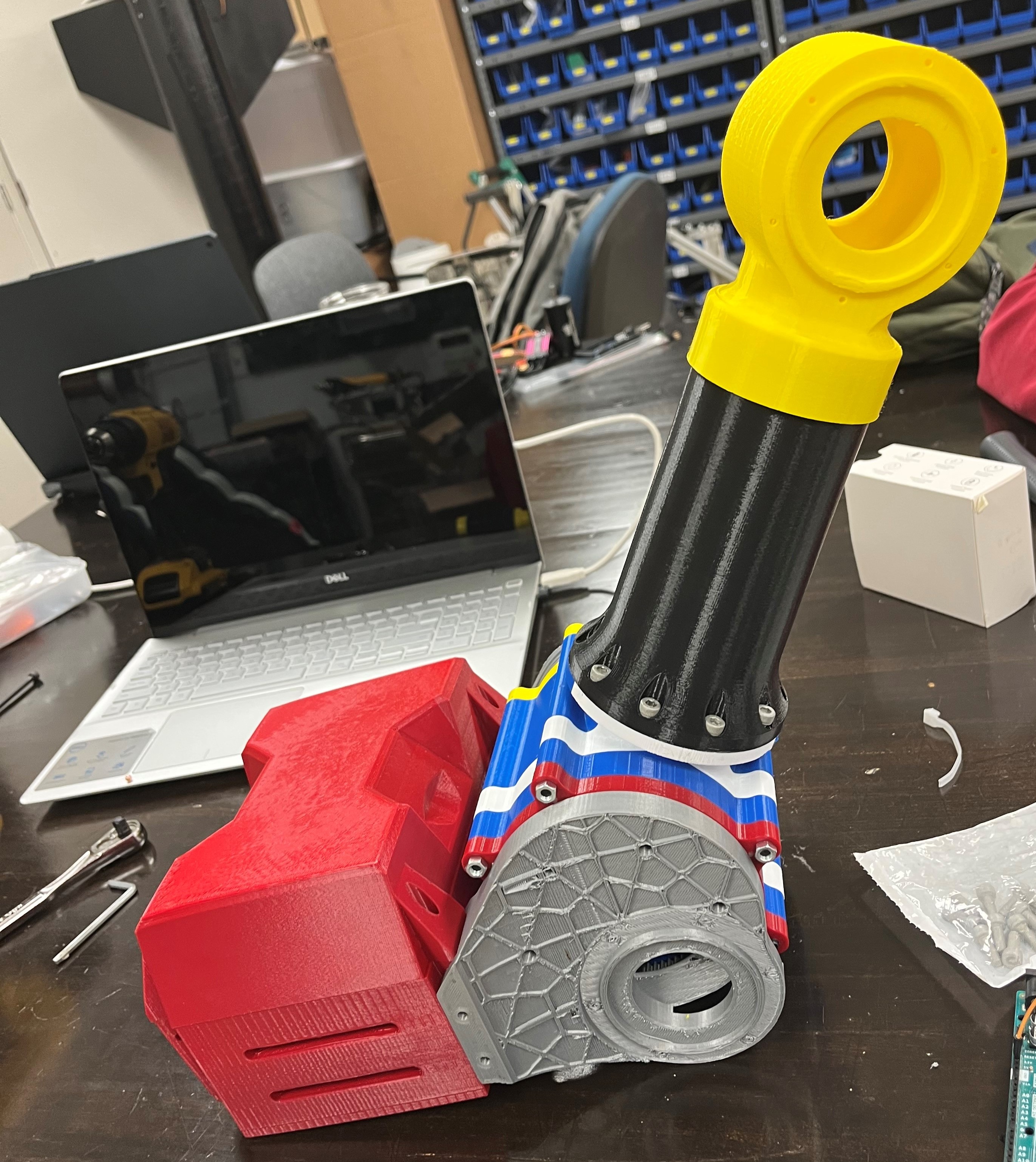
Physical Concept
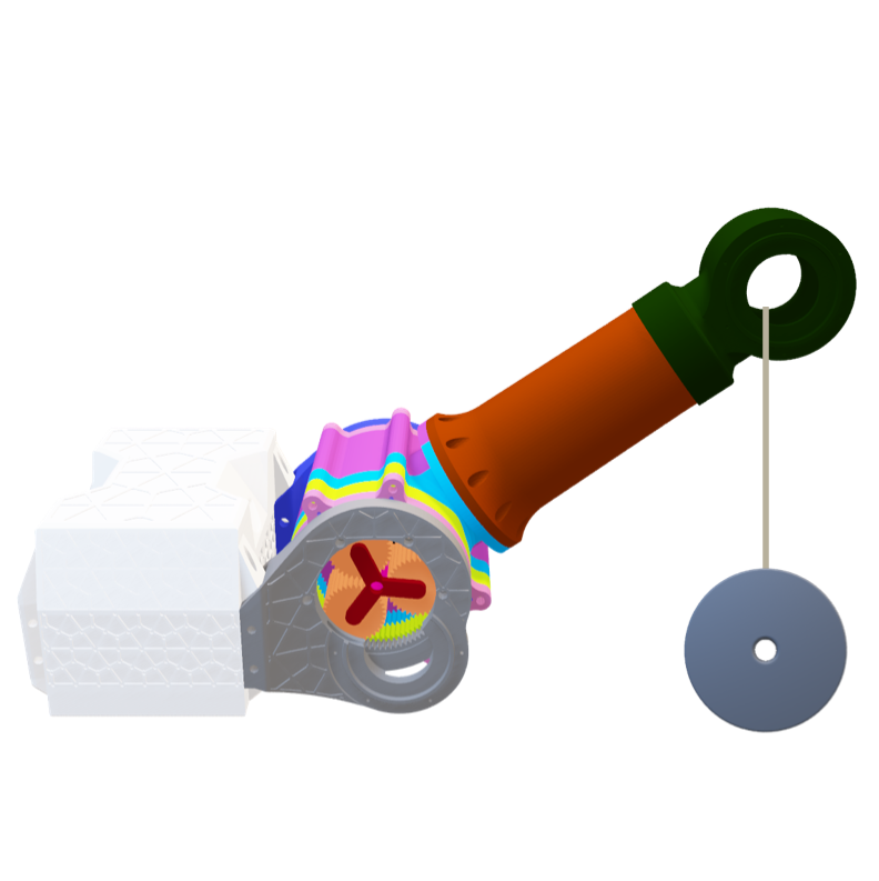
CAD Concept
Testing Videos
10 Pounds
12.5 Pounds
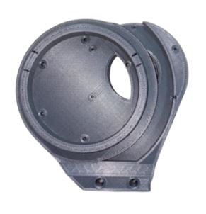
3D-Printed Components
Left Shoulder Blade
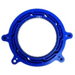
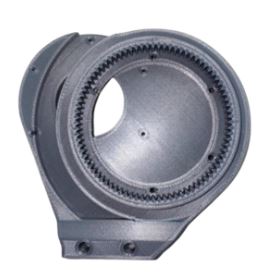
Clockwise Harmonic Gear
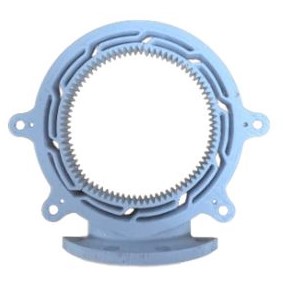
Counter-Clockwise Harmonic Gear
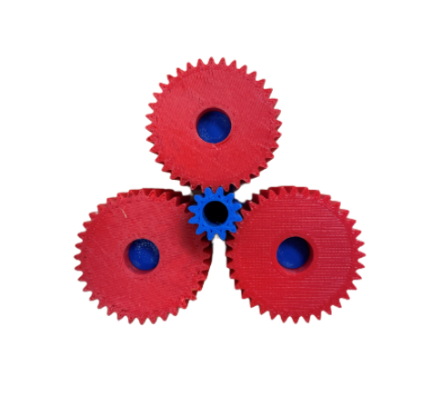
Planetary Gears (Red) and Sun Gear (Blue)
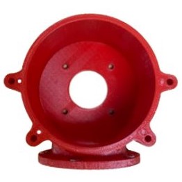
Motor Housing
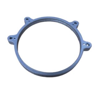
Thin Ball Bearing
Right Shoulder Blade
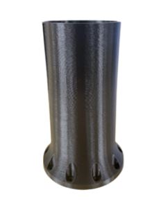
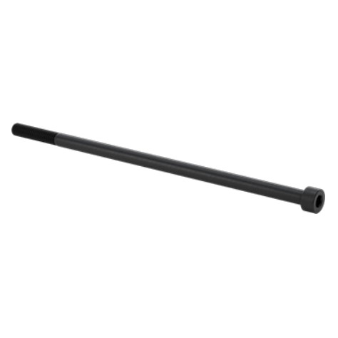
Boom
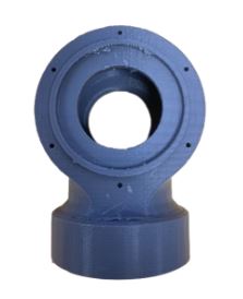
Knuckle
Electrical Purchased Components
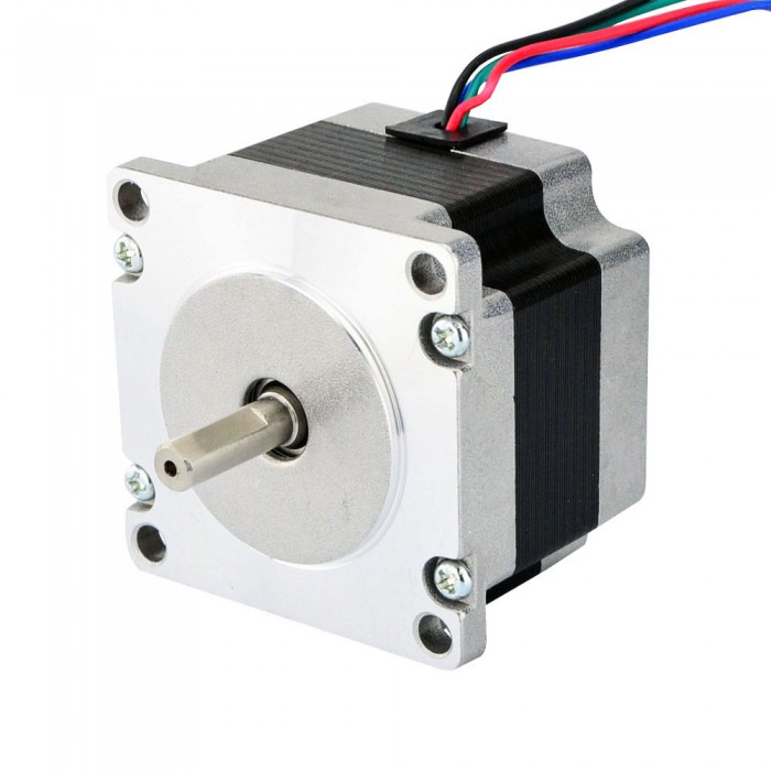
NEMA 23 Motor
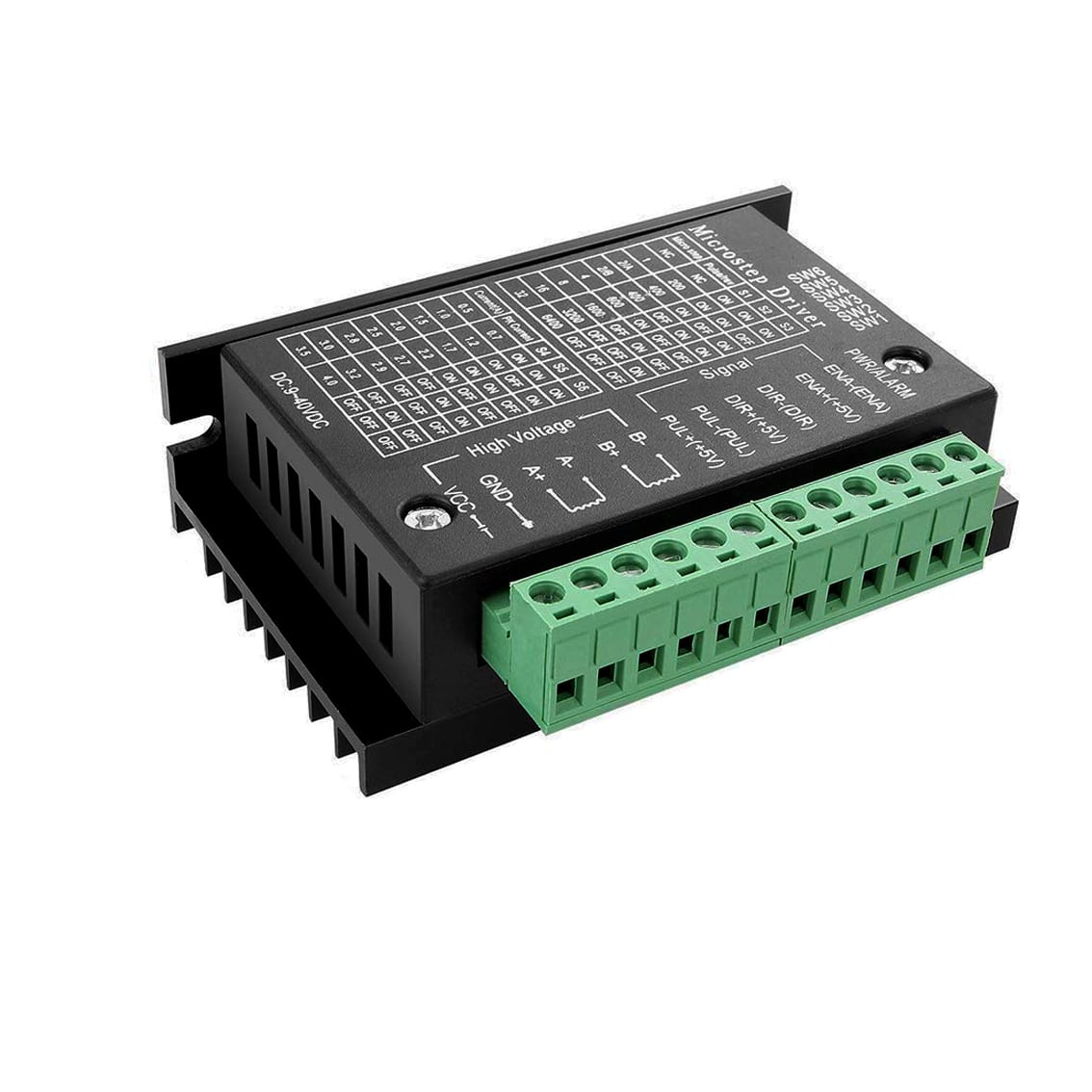
TB6600 Motor Driver
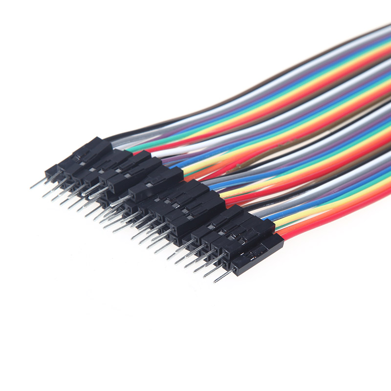
Wires
Other Purchased Components

Bullet Balls (BBs)
Dowel Pins

Lubricant for Gears

Lubricant for Bearings
Shoulder Joint Screws
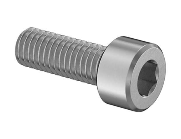
Arm (Boom) Screws
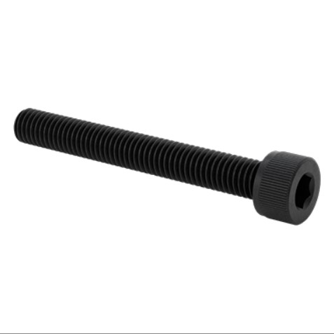
Dovetail Screws
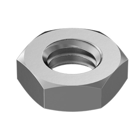
Nuts
Deliverables


Future Work
Future groups working on the RE-RASSOR Shoulder project can aspire to increase the functionality and productivity of the design. The point of failure was identified within the design of the harmonic spline. Upon attempting to lift 12.5 pounds, there was an evident cracking sound. After opening the tested assembly, no parts appeared to be broken. Therefore, it was assumed that the cracking sound came from the infill of the harmonic spline. In addition, the video displays that the gears continued moving while the arm was not lifting. This is evidence that the gears may have been slipping. Future work on the design of the spline is necessary in two major areas: the infill percentage and the width of the spline patterns. The higher the infill percentage, the lower the flexibility of the part. The shorter the spline design, the lower the flexibility of the part. Future teams can create an experimental method to identify the ideal infill percentage and spline pattern for this harmonic spline. Additionally, future work could take place in identifying the lowest infill necessary for each individual part, while maintaining an operational assembly. By decreasing the infill of each part, it would decrease the amount of material used, thus decrease the cost.