 (1)
(1)
Thermal Conduction
|
|
|
|
|
|
|
|
|
|
|
The objectives of this experiment are two-fold:
All temperatures within the bars, the water temperatures and the water flow rates are recorded under equilibrium conditions. The rate of heat flow at the heat sink is given by
 (1)
(1)
Derivation of Fourier's law
A functional relationship can be established between the rate of heat transfer and the temperature difference, length of travel and the cross-sectional area. This is the well-known Fourier's law of heat conduction
where K is the proportionality constant known as the coefficient of thermal conductivity, A is the cross-sectional area, Dx is the distance and q is the heat rate, which is obtained from Equation 1.(2)
Thermal Contact Resistance
The thermal contact resistance is directly proportional to the temperature gradient and inversely proportional to the heat flux, as indicated by the following equation
 (3)
(3)The apparatus for the experiment consists of:
Click here to see apparatus
- Conduction elements
- Heating sources
- Heat sinks
- Thermocouples and thermocouple selector
- Digital temperature indicator
- A large graduated cylinder, and a stopwatch
A description of some of the hardware used in this experiment is provided below.
1. For derivation of Fourier's law
The apparatus consists
of a variable area and a constant area thermal conductor; each mounted
vertically on a separate 0°
-700°
F hot plate, and terminated on the upper end with a fluid-cooled heat sink.
Each bar is in contact at its lower end with its own hot plate. The contact
for the tapered bar (Unit \# 3, Figure 1) is at the smallest end. Both
bars are the same diameter at the upper end at the heat sink. All heating
and conducting elements are enclosed in the insulating jacket. Figure1
illustrates the schematics of the apparatus. The dimensions of the tapered
rod are indicated in Fig. 2.
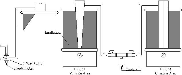
Figure 1. Conduction
apparatus for Derivation of Fourierís Law

Figure 2. Dimensions of the tapered rod conduction unit
2. For thermal contact resistance
The apparatus consists
of an insulated, tubular-shaped unit where the central section contains
a 1850°
F tube furnace which heats two axially-aligned, slightly separated, stainless
steel bars.The steel bar on the left is connected, end-to-end, to a copper
and then a steel bar; the steel bar on the right is connected to an aluminum
followed by a magnesium bar. Each bar assembly terminates in an immersion-type;
fluid cooled heat sink, which is used both to regulate and to measure heat
flux through the terminal cross-section of the bar. Means for independent
control of fluid flow rates through each heat sink is provided. All heating
and conducting elements are enclosed in an insulating jacket. A schematic
of the apparatus is shown in Figure 3.

Figure 3. Conduction apparatus for the thermal contact resistance experiment
Two stabilized stainless steel bars are used to conduct heat from the high temperature zone within the furnace into both sides of the apparatus. The stabilized stainless steel bars maintain a uniform and durable surface condition which is essential because most of the heat entering the bar is transmitted from the heating elements directly by radiation, and any change in the interface conditions of the bar after a number of operations would affect the measurements. Furthermore, the two bars extending left and right from the center of the furnace are slightly separated to prevent either bar acting as an undesired heat sink for the other. Each set of bars is tightly screwed together. Thus, the bars provide durable heat conduction and at the same time provide for measurable barrier effects.
At the left, attached axially to the stainless steel bar, there is a bar of conditioned copper with a steel bar attached to it in a similar manner. At the right, aluminum and magnesium bars are similarly arranged. Each set of bars is tightly screwed together. Thus, the bars provide durable heat conduction and at the same time provide for measurable barrier effects.
1. For derivation of Fourier's law
Two hot plates are used as the heat source, one for the variable area conductor (Unit #3) and one for the constant area conductor (Unit #4). Each hot plate draws approximately 6 amps at 120 volts and has its own dial control knob. The dial knob is a combination on-off switch and heating rate selector with a built-in thermostat and an indicator light. With the knob at the counterclockwise end of the dial scale, the current is switched off. Turning the knob clockwise starts the flow of current, and allows the operator to select a desired heat rate up to the maximum of 750 watt.
2. For thermal contact resistance
The tube furnace is specifically oriented to heat two horizontal stainless steel bars in axial alignment. The left-handed stainless steel bar is coupled to a copper bar, the copper bar to a steel bar, which in turn is coupled to a copper element of the heat sink (Unit #1). The right hand stainless steel bar is coupled to an aluminum bar and the aluminum bar to a magnesium bar, which is again coupled to a copper element of the heat sink (Unit #2). Heat flows in series through these units. Thermocouples located along these axes of the bars are spaced longitudinally to enable the experimenter to take temperature measurements at critical points along the entire length of the heat flow. The furnace is rated at 750 watts and requires 115 V AC. The furnace base contains a multi-step temperature-controlling transformer; all internal wiring originates from this point.
To regulate temperature, proper adjustment of the control on the front panel must be made. To obtain the fastest heating, the switch should be set on the Number 10 position. However, you must be very careful to reduce the maximum input at the proper time to prevent over-heating and possible burnout of the heater units. Maximum safe operating temperature for the furnace is 1850° F. This corresponds approximately to the Number 6 position for 120 V AC. operation.
Heat Sink
The heat path of each unit ends in a liquid-cooled heat sink for independent measurement of heat flux. The heat sink is a well in the upper end of the vertical conductor bar, as shown in Figure 4. For Units #1 and #2, a copper element, attached to the end of each set of bars, extends horizontally into the coolant chamber as shown in Figure 5. The heat sink inlet manifold has one thermocouple and each heat sink outlet has its own thermocouple. Location of heat sink thermocouples are shown in Figure 6.
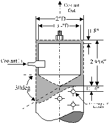
Figure 4. Heat sink assembly for Units 3 and 4
![]()
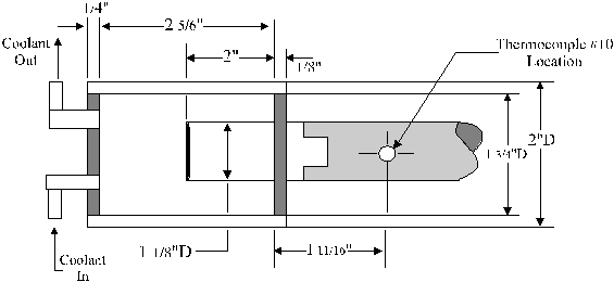
Figure 5. Heat sink
assembly for Units 1 and 2
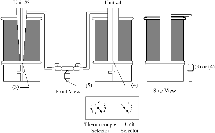
Figure 6. Location of heat sink thermocouples
Temperature Measurement
Glass-insulated Chromel-Alumel thermocouples are used for all temperature measurements. Ten thermocouples are mounted at the center of each metal bar at the positions shown in Figures 7 (for Unit #1) and 8 (for Units #3 and #4) (Dimensions given in inches). Unit #2 is configured similar to Unit #1, hence it is not shown. The inlet temperature to each heat sink is obtained from a single thermocouple mounted in the inlet manifold to the heat sink. The heat sink outlets have their own thermocouples.
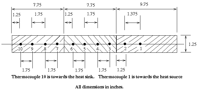
Figure 7. Thermocouple
positions for Unit #1 (and #2)
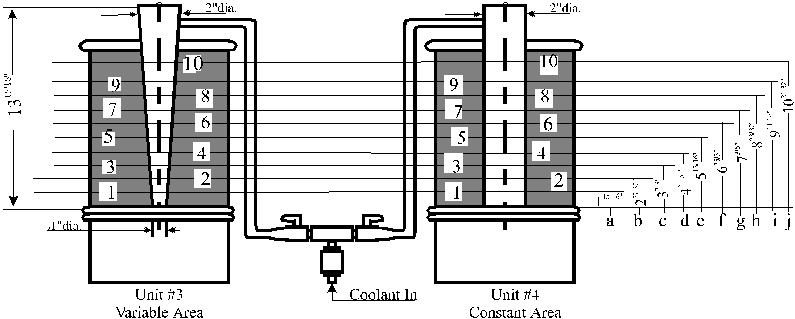
Figure 8. Thermocouple positions for Unit #3 and #4
Thermocouple Selector
All thermocouple
pairs lead into a junction box with a selector switch bank, which connects
any thermocouple to a common terminal post to allow rapid read-out of all
thermocouples using only one digital display gage. In the selector switch
bank, each position on the unit-selector switch is numbered to its corresponding
unit. The thermocouple number selector switch is designed the same
way; each thermocouple position is numbered to its corresponding thermocouple
number on the unit. Units #1 and #2 refer to the units on the thermal contact
resistance unit; Unit #3 corresponds to the tapered rod, and Unit #4 corresponds
to the uniform rod. The heat sink thermocouples have been grouped
for convenience as Unit #5, on the Unit Selector. Thermocouple # 5, on
Unit # 5,corresponds to the heat sink inlet temperature, while thermocouples
#1,#2, #3 and # 4 for Unit # 5 correspond the heat sink outlet temperatures
for Unit #1, Unit #2, Unit #3 and Unit # 4, respectively. Unit Selector
switch. Location of the various thermocouples is shown in Figure
9.
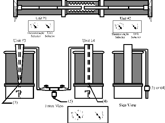
Figure 9. Heat sink locations.
All the units are heated up at least four hours prior to the experiment. The hot plates and the furnace are regulated for the desired heating. The coolant flow rate is regulated to register a noticeable temperature difference between the inflow and the outflow temperatures. The lab assistant will perform all this work.
The volume of water, Vw displaced in time Dt will be measured with a large graduated cylinder. The temperature readings will be measured using a compensating reference temperature, thermocouple digital display gage. For Units #3 and #4, the temperature data will be taken at all the thermocouple locations at two different hot plate temperatures.
Click here to see apparatus
- Select Unit # 3 on the unit selector switch (USS).
- Using the thermocouple selector switch (TSS), step through the 10 thermocouples (TCís) for Unit #3.
- Record the temperature indicated by each TC.
- Select Unit #5 on the USS. The TCís #5 and #3 on Unit #5 indicate the coolant water inlet and outlet temperature for Unit #3.
- Record the coolant inlet and outlet temperatures for Unit #3.
- In order to obtain Vw/Dt, hold the outflow hose from the Unit #3 over the graduated cylinder.
- Record the time,Dt, required to fill up the cylinder to a desired volume, Vw.
- Record the volume, Vw.
- After consulting the lab assistant, raise the hot plate temperature to the next setting.
- Now select Unit # 4 on the USS.
- Go through Steps 2-9 for Unit #4. Remember that for Unit #5 on the USS, TCs #5 and #4 indicate the coolant water inlet and outlet temperature for Unit #4.
- Proceed to the analysis for units 1 and 2.
- Select Unit #1 on the USS.
- Go through Steps 2-8 for Unit #1. Remember that for Unit #5 on the USS, TCs #5 and #1 indicate the coolant water inlet and outlet temperature for Unit #1.
- Select Unit #2 on the USS.
- Go through Steps 2-8 for Unit #2. Once again, remember that for Unit #5 on the USS, TCs #5 and #2 indicate the coolant water inlet and outlet temperature for Unit #2.
- Wait for at least 30 minutes for the temperatures on Units #3 and #4 to reach steady state.
- Follow Steps 1-11.
- GIVE A COPY OF YOUR DATA TO THE LAB ASSISTANT.
NOTE:The data
for units # 3 and # 4 will be collected from all the groups of the week
by the lab
assistant, and compiled onto a single data table to be used by all the
groups for that week.
Fourier's law
![]()
Experiment 3 Data Sheet
Note: Please note the units of the quantities which are being measured, when recording data. For example, when measuring voltage, if the voltmeter reads 16 mV, then write down 16 mV instead of just 16.
Group ______ of
____/___/___ (_______day)
NOTE:
A copy of the readings for the Part I has to be handed to the lab TA after
the experiment. A single data table incorporating the data from the various
groups for the week will be put up at the laboratory web site on the Monday
of the following week. This collected data will be used for calculating
the thermal conductivity.
I:
Derivation of Fourier's law:
|
|
|
||||
|
-couple Number |
Tapered Rod Temperature |
Uniform Rod Temperature |
Tapered Rod Temperature |
Uniform Rod Temperature |
|
|
|
|
|
|
|
|
|
|
|
|
|
|
|
|
|
|
|
|
|
|
|
|
|
|
|
|
|
|
|
|
|
|
|
|
|
|
|
|
|
|
|
|
|
|
|
|
|
|
|
|
|
|
|
|
|
|
|
|
|
|
|
|
|
|
|
|
|
|
|
|
|
|
|
|
|
|
|
|
|
|
|
|
|
|
|
|
|
|
|
|
|
|
|
|
|
II: Thermal Contact Resistance:
|
|
|
|
|
|
|
|
|
|
|
|
|
|
|
|
|
|
|
|
|
|
|
|
|
|
|
|
|
|
|
|
|
|
|
|
|
|
|
|
|
|
|
|
|
|
|
|
|
|
|
|
|
|
|
|
|
|
|
|
|
|
|
|
The water temperatures are measured off Unit 5 as shown in the following table.
|
|
|
|
|
|
|
|
|
|
|
|
|
|
|
|
|
|
YOU NEED TO GET THE LAB INSTRUCTOR'S SIGNATURE BEFORE LEAVING.
The student has performed the experiment satisfactorily and has cleaned the work area.
___________________________ _______________
(Lab assistant's signature) Date