Fig. 1 - Radiative properties of a surface
Properties
of Thermal Radiation
|
|
|
|
|
|
|
|
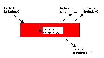
Fig. 1 - Radiative properties of a surface
Fig. 1 shows that when radiant energy G (W/m2) is incident on a surface, portions of it can be reflected, absorbed and/or transmitted. The relative fractions that are reflected, absorbed and transmitted are determined by the radiative properties r, a and t, the reflectivity, absorptivity and transmissivity, respectively, of that surface. From conservation of energy we also know that:
r + a + t = 1
In addition to the above, the surface also emits energy via radiation where the amount of energy emitted by the surface is given by the Stefan-Boltzmann Law:
Thermal
Radiation Spectrum
Electromagnetic radiation, like all other forms of radiation, travels at the speed of light, which is related to its wavelength, l, and frequency n by
c=vl
where c = 3 x10⁸m/s is the speed of light. Thermal radiation spans only a portion of the entire electromagnetic spectrum, which ranges from X-rays to Microwaves. The thermal spectrum spans
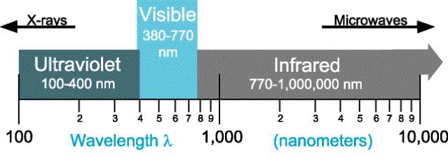
Fig. 2 Thermal radiation portion of the Electromagnetic Spectrum
(Courtesy of EML 3015, C. Shih)
a range of 0.1mm - 100mm, which, as shown in Fig. 2 includes the entire visible spectrum. Whether thermal radiation is visible, and at what color, is a function of the portion of the radiation that falls within the visible spectrum. Not only is the total amount of thermal radiation emitted by a surface - described by the Stefan-Botzmanns law - a direct function of temperature, how this energy is distributed over the thermal spectrum as a function of wavelength, is also a related to the surface temperature.
The
Planck Distribution gives the spectral distribution of thermal radiation
of a Black Body as a function of temperature. This distribution function
can be found in any standard undergraduate heat transfer text. Using Plancks
Distribution, the spectral distributions from black bodies at various temperatures
are shown in Fig. 3. The figure shows that energy radiated varies continuously
with wavelength at any given temperature. It also illustrates that at lower
temperatures most of the energy the energy is outside the visible spectrum.
However, as the temperature rises, more and more energy is shifted to shorter
wavelengths and into the visible spectrum region. The dependence of spectral
distribution on temperature also explains why the
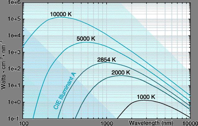
Fig. 2 Spectral distribution of a Black body emissive power using Plancks Distribution
(adapted from EML 3015 notes by Dr. Shih)
color of a body changes as it is heated: from black to dark red to bright red to yellow and finally to white hot. The overall intensity of the visible light from an object also increases with temperature since a larger percentage of the total energy radiated is in the visible spectrum.
Solar
radiation has a spectrum very similar to that of a black body at 5800K.
As a result, a large portion of solar radiation is visible. The reflectivity,
absorptivity and transmissivity of most materials are also a function of
wavelength of the incident radiation. Hence they may transmit radiation
from sources above (or below) certain temperatures, i.e. within a certain
range of wavelengths, while blocking light from sources at temperatures
outside that range. This wavelength dependence of material transmission
properties is responsible for the greenhouse effect and will also be explored
in this experiment.
The
following main components will be used to conduct different parts of this
experiment.
Stefan-Boltzmann Lamp:
This lamp will serve as a high temperature source of thermal radiation. By adjusting the voltage and current supplied to this lamp, filament temperatures as high as 3000°C can be obtained. The voltage and current supplied to this lamp can be monitored using a voltmeter and an ammeter, respectively. These values can be used to determine the resistances of the filament at various temperatures, which can then be used, calculate the temperature of the filament.
(IMPORTANT:
Never supply more than 13V and 3A to this lamp)
Variable Power Supply:
This power supply will be used to operate the Stefan-Boltzmann lamp. Be very careful while using this supply, the current output is very high.
IMPORTANT:
Never supply more than 13V and 3A to the lamp)
Radiation Sensor:
The
Pasco TD-8553 radiation sensor produces a voltage output, which is proportional
to the intensity of radiation incident upon the sensor. The output voltage
ranges from microvolts to 100 millivolts.
Thermal Radiation (Leslies) Cube:
The cube has four different surfaces with different radiative properties. It can be heated up to temperatures of 120°C by a light bulb placed inside the cube. The cube temperature is measured by measuring the resistance of a thermistor embedded inside the cube. Once the resistance is measured the temperature can be obtained using the temperature vs. resistance calibration provided to you by the Teaching Assistants.
Multimeters:
Three
multimeters will be provided to measure the voltages, currents, and resistances
of the above components.
NOTE:
Please record all you measurements in appropriate tables or spaces in the
data sheets.
I. Verification of Stefan-Boltzmann Law
The
Stefan-Boltzmann Law will be verified in this experiment. You will also
measure the transmission properties of glass as a function of temperature
of the radiation source.
1. Connect the voltmeter, the ammeter and the Power supply to the Stefan-Boltzmann lamp as shown in Fig. 4 .

Figure 4
The voltmeter should be connected to the binding posts of the lamp.
2. Connect the radiation sensor to a multimeter and place it approximately 6 cm away from the lamp, as shown.
3. Remove all other objects in the vicinity of the radiation sensor to ensure that its output is not influenced by extraneous radiation sources.
4. Before turning on the lamp, measure and record the ambient room temperature,Tref and the resistance of the lamp filament, Rref.
5. Turn on the power supply and set it to the lowest voltage reading, V, in Table 1 in the data sheet. Measure and record the current, I, and the radiation sensor output voltage.
6. Repeat step 5 for each voltage setting, V, in Table 1.
7. At V = 3 Volts place the glass square between the sensor and the bulb and record the radiation sensor output, repeat for V = 10 Volts.
Note: Record the sensor reading at each setting quickly. In between readings, cover the sensor with the insulating foam blocks provided. This prevents the sensor surface from overheating and providing erroneous readings.
Calculations for Determining the Filament Temperature
1. Determine the filament resistance, RT, at each voltage setting.
2. Divide the filament resistance, RT, by the reference resistance measured at room temperature, Rref to obtain RT /Rref.
3. Using
either the table or the graph of RT /Rref
as a function of temperature, determine the filament temperature.
II. Radiation Intensity as a Function of Distance
You
will measure the magnitude of incident radiation on a surface as a function
of distance from the thermal source in this experiment.
1. Arrange and connect the Stefan-Boltzmann lamp, the radiation sensor, the voltmeter and the power supply as shown in Fig. 5
Figure 5
2.
Adjust the height of the sensor such that it is at the same level as the
lamp filament.
Figure 6
2. Once the cube has reached equilibrium conditions at a power setting of 5, place the radiation sensor such that its two prongs are touching one of the cube surfaces. You will know that the cube has reached equilibrium conditions when the resistance fluctuates around a fixed value.
3. Record the sensor output voltage in Table 4 . Repeat this with the sensor facing each of the four surfaces. Also record the thermistor resistance; this will be used to obtain the thermistor temperature.
4. Repeat steps 2 and 3 for power settings of 7 and 9. At each new setting wait for the cube to reach equilibrium conditions.
Note:
As before, to prevent the sensor from heating up, cover the sensor with
the insulating foam blocks, in between readings.
I. Verification of Stefan-Boltzmann Law
1. Plot the measured measured radiation as a function of T4. Is this relationship linear over the entire range of measurements? If not, discuss the reasons for this non-linear behavior.
2. The Stefan-Boltzmann Law is exactly applicable for perfect black bodies. Do your results indicate that the light bulb behaves as an ideal black body? If it does, over what temperature range, discuss reasons for departure from black body behavior.
3. Compare the radiation sensor output at the voltages with and without the glass plate. Is glass a better transmitter of radiation at higher or lower temperatures and why?
4. In light of the results discussed in question 3, what is the link between this behavior and the Greenhouse Effect. Also, does it explain why the inside of a car parked in the sun heats up so rapidly?
II. Radiation Intensity as a Function of Distance
1. Plot the net radiation from the source, i.e. radiation with lamp on radiation with lamp off, as a function of distance. Discuss reasons for the trend observed in this plot, e.g. if it is linear or exponential, etc. and why.
2. If the plot in question 1 is not linear, plot the net radiation as a function of 1/X2. It is known that radiation from a point source decays linearly with distance squared. Explain this observation. Does your plot support this assertion over the entire range of measurements?
III. Emissivity of Various Surfaces
1. List the four surfaces of the Leslies Cube in terms of emitted radiation in descending order. Is this order dependant on the source temperature (voltage)?
2. For
all three experiments, lists some sources of error that might have affected
your measurements. Briefly discuss the effect and significance of
these sources on your results.
Reference:
Introduction
to Thermodynamics and Heat Transfer, Yunus A. Cengel, Chapter 12: Radiation
and Heat Transfer, McGraw Hill, 1997, pp. 625 700.