Figure 1. Thermoelectric Circuit
Dynamic response of temperature
measuring device
(Transient heat transfer)
|
|
|
|
|
|
|
|
To introduce the basic principles of several common methods of temperature measurement (liquid-in-glass thermometers, thermocouples and thermistors). Also, to familiarize the students with the static calibration procedure and the dynamic characteristics of a first order system.
Thermocouples
When a pair of electrical conductors (metals)
are joined together, they will generate a thermal emf when the junctions
are at different temperatures. This phenomenon is known as the Seebeck
effect. Such a device is called a thermocouple. The resultant emf
developed by the thermocouple is in the millivolt range when the temperature
difference between the junctions is 100 0C. In a single
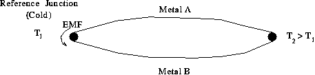
thermoelectric circuit, such as shown in Figure 1, the current flows from
metal A to metal B at the colder junction (reference junction). In
such a situation, metal A is generally referred as being thermoelectrically
positive with respect to metal B.
Figure 1. Thermoelectric Circuit
In determining the emf of a thermocouple as a function of the temperature, one junction is maintained at some constant reference temperature, such as ice-water mixture at a temperature of 0 0C. The other junction is maintained at the temperature corresponding to the emf, which can be measured by a digital voltmeter, as shown in Figure 2.
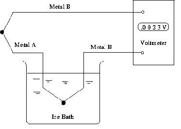
Figure 2 Determining the EMF of a Thermocouple
Hence, after proper calibration, the thermocouple may be used to measure temperature. The output voltage, E, of a simple thermocouple circuit is usually written in the form,
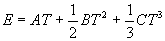 (1)
(1)
where T is the temperature in 0C, and E is based on a reference junction temperature of 0 0C. The constants A, B and C are dependent on the thermocouple material.
Thermistor measurement - The transducer circuit
The thermistor, a thermally sensitive resistor, is a solid semi conducting material. Unlike metals, thermistors respond inversely to temperature, i.e., their resistance decreases as the temperature increases. The thermistors are usually composed of oxides of manganese, nickel, cobalt, copper and several other nonmetals. The resistance is generally an exponential function of the temperature, as shown in Equation 2:
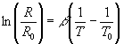 (2)
(2)
where R0 is the resistance at a reference temperature, T0, while b is a constant, characteristic of the material. T0, the reference temperature, is generally taken as 298 K (25 0C). Since all measurements made with thermistors can be reduced to detecting the resistance changes, the thermistor must be placed in a circuit and the resistance changes recorded in terms of the corresponding voltage or current changes. The formula relating the voltage (or current) changes to the resistance changes for a given circuit has to be determined theoretically or empirically, or by a combination of both.
In the design of thermistor circuits, one must take the precaution that within the range of the operating conditions, the circuit remains stable at all times. Thermistor resistance varies inversely with temperature. The voltage applied directly across a thermistor causes its temperature to rise, and its resistance to decrease. Sufficiently high voltage may cause thermal "runaway" (curve A in Figure 3), in which condition, higher currents and temperatures are induced until the thermistor fails, or the power is reduced. A series resistor, introduced to limit current, ensures stability (curve B). Thermal "runaway" will, in all probability, permanently damage the thermistor, or change its characteristic properties.
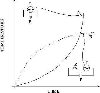
Figure 3. Thermistor Behavior and Thermal Runaway
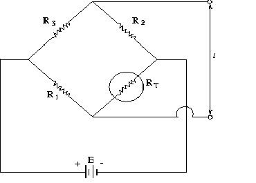
To increase the precision of the measurement, one should add a voltage divider to the circuit shown in Figure 4(a). This will convert it to a Wheatstone bridge circuit, as shown in Figure 4(b). The out-of-balance voltage, DV, can then be measured and related to the resistance of the thermistor. A correct choice of resistors R2 and R3 will remove the mean DC value of DV. Note that although the bridge circuit can increase the precision of the readings, the sensitivity is still the same as for the simple voltage divider circuit shown in Figure 4(a). The simple DC bridge circuit of Figure 4(b) is generally satisfactory for most applications.
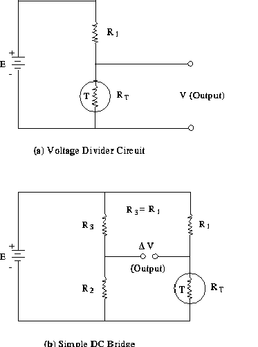
Figure 4. Setting up a Thermistor Circuit
Considering this circuit, we shall now derive the relation between T and DV. In general,
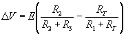 (3)
(3)
Assume R1 = R3. Then,
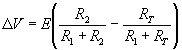 (4)
(4)
Rearranging for RT,
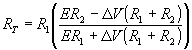 (5)
(5)
The relation between T and RT is given by,
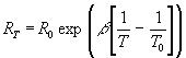 (6)
(6)
or,
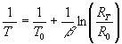 (7)
(7)
Substituting for RT from Equation 5, we have
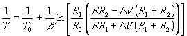 (8)
(8)
If we further assume R1 = R2 = R3 = Rb, we have,
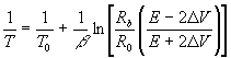 (9)
(9)
T is not a linear function of V, and so any linear
analog recorder will be in error when linear interpolation is used between
calibration points (for small ranges in temperatures, the error may be
negligible). If we measure E along with our scans of the DVs, then
the only unknowns in Equation 9 are R0 and b. These unknowns
are determined by calibration experiments.
Back to the top
The following apparatus is used in conducting the experiments:
1. Constant temperature bath
Examine the components of the bath which include the fluid chamber, heater, coolant, thermo-regulator, stirring and circulation pumps. Several different temperature settings will be used. Note how the settings are made and set the bath for a low temperature.
2. Liquid-in-glass thermometers
Note the difference between full immersion and partial immersion thermometers and note how each is to be used. The teaching assistant will demonstrate the difference between the full and the partial immersion thermometer.
3. Thermocouples
The thermocouple used in this experiment is made by welding a long piece of wire of material A and two shorter pieces of wire of material B, thus forming two dissimilar junctions as shown in Figure 5. Connect the free ends to a digital voltmeter (set to read mV), and perform the following experiments:
Click here to see apparatus
- With both junctions in air, observe and record the output.
- Hold one junction of the thermocouple between your fingers and the other junction in the ice bath. Observe and record the voltmeter reading.
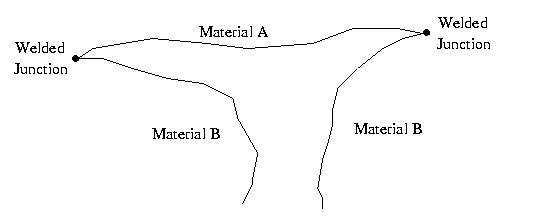
Figure 5. Thermocouple Arrangement
4. Resistance Temperature Detector (RTD)
The RTD will be immersed in the constant temperature bath for the duration of the experiment. The temperature indicated by the RTD will serve as the reference temperature (i.e., actual temperature of the bath).
5. Thermistor
Examine the thermistor provided. You will calibrate it by placing it in the constant temperature bath along with the thermocouple. The calibration will be done at the same temperature and at the same time as the thermocouple calibration. The thermistor is to be placed in a Wheatstone bridge circuit, as shown in Figure 6. Examine the bridge circuit and note where all the connections are to be made. Perform the following measurements before connecting the circuit:
Place one junction of the thermocouple in the ice bath, which serves as a reference junction, and the other junction in the constant temperature bath. Place the thermistor in the constant temperature bath. Starting with the bath at the lowest setting,
7. Time response
Connect the outputs from both sensors to the Analog to Digital Converter (ADC) in the computer. Using the provided LabView program, monitor and record the outputs of the thermocouple and the thermistor as you perform the following:
![]()
Experiment 4 Data Sheet
Note: Please note the units
of the quantities which are being measured, when recording data.
For example,
when measuring voltage, if the voltmeter reads
16 mV, then write down 16 mV instead of just 16.
I. Inspect the constant temperature bath.
II. Thermocouple analysis:
1. Record output voltage of thermocouple:
Both terminals in air:_________
One terminal held between fingers and the other terminal in an ice bath:________
III & IV. Thermocouple and Thermistor calibration
1. Record the following:
a) Supplied voltage, E: __________
b) Wheatstone bridge resistor values:
R1 = _______________, R2 = ______________, and R3 = ______________
2. Place one junction
of the thermocouple in the ice bath and the other in the constant temperature
bath. Also place the
thermistor in the constant temperature bath. Record the temperature of
the
constant temperature
bath (via RTD), the thermocouple voltage (V) and the out-of-balance voltage
of the thermistor (DV)
in the following table. Repeat for ten different bath temperatures.
|
|
|
|
|
|
|
|||
|
|
|||
|
|
|||
|
|
|||
|
|
|||
|
|
|||
|
|
|||
|
|
|||
|
|
|||
|
|
|||
|
|
V: Time response:
DO NOT DISCONNECT THE WHEATSTONE BRIDGE CIRCUIT.
With the circuit in place, connect thermistor
(DV) output and thermocouple output to the ADC
card in the computer. The data will be recorded using a
LabView program, your lab TA will assist you
with this part of the experiment.
Note on Breadboard use:
The supplied breadboard should be used to develop
the wheatstone bridge circuit as discussed in the lab
handbook. The breadboard is simply a convenient
tool for building up circuits. The breadboard consists of
rows of small, electrically connected connection
points in a grid pattern. Interconnected connection points form
a bus. The board has three sections that
are divided to allow for easy circuit connection. Each section has
two
long buses running from top to bottom labeled
A and B. These buses are normally used for power connections
from the terminal posts located on the top of
the board or from the two long buses running left to right on the top
of the board (also labeled A and B). Small
buses consisting of five connection points are situated on the left
and right of the power bus. These buses
are only connected from left to right and are not connected to the
power bus. Each section of the board is
independent of the others. The breadboard configuration allows for
very complex circuits to be constructed and allows
for quick construction of the wheatstone bridge circuit
needed for this experiment. The supplied
wire set and resistors are pushed into the connection points in the
required configuration as illustrated in the
lab handbook. Consult the lab TA for further assistance.
YOU NEED TO GET THE LAB INSTRUCTOR'S SIGNATURE BEFORE LEAVING.
The student has performed the experiment satisfactorily
and has cleaned the work area.
___________________________ _______________
(Lab assistant's signature)
Date