|
|
|
|
|
Next: 6.26 Zener and Avalanche Diodes |
|
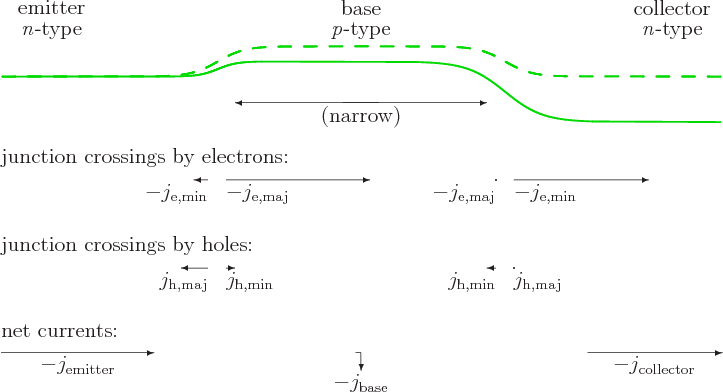
A second very important semiconductor device besides the p-n diode is the transistor. While the p-n diode allows currents to be blocked in one direction, the transistor allows currents to be regulated.
For example, an n-p-n transistor allows the current of
electrons through an n-type semiconductor to be controlled. A
schematic is shown in figure 6.35. Electrons flow through
the transistor from one side, called the emitter,
to
the other side, called the collector.
To control this current, a very narrow region of p-type doping
is sandwiched in between the two sides of n-type doping. This
p-type region is called the base.
If the
voltage at the base is varied, it regulates the current between
emitter and collector.
Of course, when used in a circuit, electrodes are soldered to the emitter and collector, and a third one to the base. The transistor then allows the current between the emitter and collector electrodes to be controlled by the voltage of the base electrode. At the same time, a well-designed transistor will divert almost none of the current being regulated to the base electrode.
The transistor works on the same principles as the p-n junction of the previous section, with one twist. Consider first the flow of electrons through the device, as shown in figure 6.35. The junction between emitter and base is operated at a forward-bias voltage difference. Therefore, the majority electrons of the n-type emitter pour through it in great numbers. By the normal logic, these electrons should produce a current between the emitter and base electrodes.
But here comes the twist. The p region is made extremely thin, much smaller than its transverse dimensions and even much smaller than the diffusion distance of the electrons. Essentially all electrons that pour through the junction blunder into the second junction, the one between base and collector. Now this second junction is operated at a reverse-bias voltage. That produces a strong electric field that sweeps the electrons forcefully into the collector. (Remember that since the electrons are considered to be minority carriers in the base, they get sweeped through the junction by the electric field rather than stopped by it.)
As a result, virtually all electrons leaving the emitter end up as an electron flow to the collector electrode instead of to the base one as they should have. The stupidity of these electrons explains why the base voltage can regulate the current between emitter and collector without diverting much of it. Further, as seen for the p-n junction, the amount of electrons pouring through the junction from emitter to base varies very strongly with the base voltage. Small voltage changes at the base can therefore decimate or explode the electron flow, and almost all of it goes to the collector.
There is one remaining problem, however. The forward bias of the junction between emitter and base also means that the majority holes in the base pour through the junction towards the emitter. And that is strictly a current between the emitter and base electrodes. The holes cannot come from the collector, as the collector has virtually none. The hole current is therefore bad news. Fortunately, if you dope the p-type base only lightly, there are not that many majority holes, and virtually all current through the emitter to base junction will be carried by electrons.
A p-n-p transistor works just like an n-p-n-one, but with holes taking the place of electrons. There are other types of semiconductor transistors, but they use similar ideas.
Key Points
- A transistor allows current to be regulated.