Figures
for ICSS white paper,
“Ultra-low-power adiabatic circuits driven by high-Q MEMS resonators,”
by M. Frank (ECE dept., FAMU-FSU
College of Engineering)
and H. Xie (ECE dept., University
of Florida
Shortcuts to figures:
1 2 3 4 5
6 7 8 9 10 11 12 13.
Figure 1. We designed a fully-adiabatic shift register in Cadence using TSMC .18 micron technology libraries. Here is the schematic, by graduate student Krishna Natarajan.
Figure 2. The shift register design was laid out and taped out on an integrated CMOS/MEMS test chip together with our MEMS resonator structures. Here is an early version of the shift register layout.
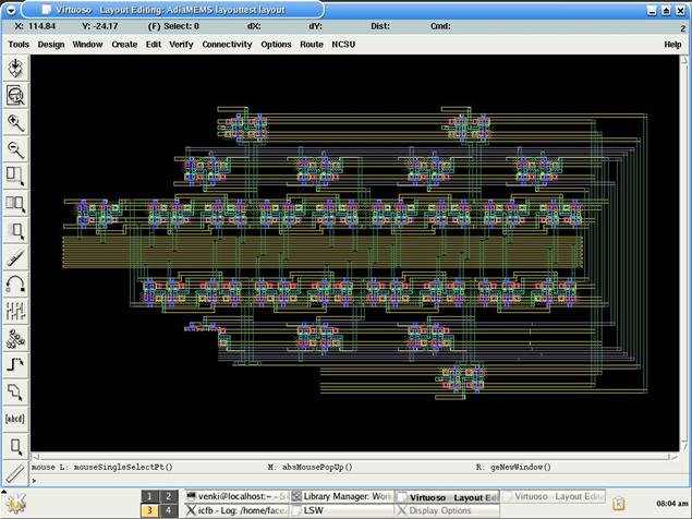
Figure 3. We also designed a fully-adiabatic 32-bit adder using an optimized version of a standard carry-skip adder structure.
Figure 4. High 16 bits of the Cadence schematic for the adder circuit, by graduate student Krishna Natarajan.
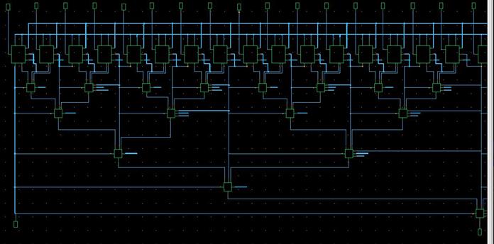
Figure 5. We simulated the shift register in Cadence, and plotted power dissipation per nFET versus frequency, and compared it against a standard CMOS inverter. A 100x power-performance boost was demonstrated.
Figure 6. We also simulated the adder, with ideal waveforms, and compared it against a standard CMOS ripple-carry adder. We obtained a 20x power-performance boost.
Figure 7. Basic schematic of the MEMS resonator structure. The resonator controls a variable capacitance in a voltage divider structure with the logic load capacitance. Custom-shaped comb fingers control the wave shape.
Figure 8. The first of our custom prototype MEMS resonator designs that was taped out; masks developed for a TSMC .35 micron process, by Ph.D. student Maojiao He. Currently the raw parts have been received and are undergoing DRIE etching.

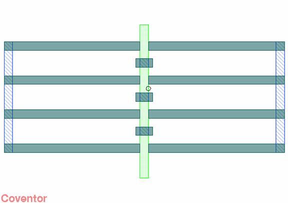
Figure 9. Layout of another experimental structure that achieves a more symmetrical wave shape. The arm extending in the y direction oscillates in the x direction and supports deep vertical fins which pass back and forth between alternating sets of deep vertical plates.