Explanation of Velocity Diagram

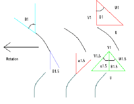
A velocity diagram is an important tool in the design of a compressor. The first row of blades in the compressor are the rotors, in the diagram below you can see that they are rotation to the left. The red triangle will help us to determine the angle of attack for the rotor blades. The vector V1 is the inlet speed and direction of the fluid flow into the compressor. The vector U in the red triangle represents the rotation of the rotor blades. W1 is the fluid velocity relative to the rotor blades, and B1 is the inlet angle of the rotor blades.
The green triangle represents the fluid flow after the rotor. In this triangle the vector W1.5 represents the fluid flow relatives to the rotor blades, V1.5 represents the velocity and direction the fluid flow will leave the rotor blade at. V1 again is the inlet velocity of the fluid and U is the rotor speed. Using is triangle we can determine the exit angle for the rotor blades B1.5, and the inlet angle for the stator blades.