Compressor Example Problem
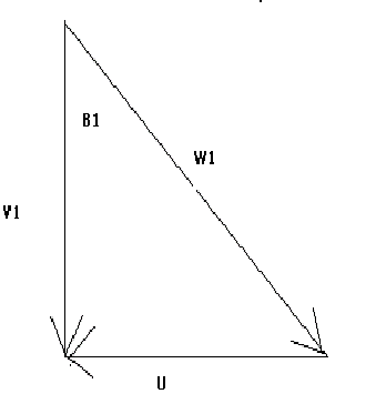
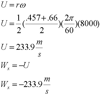
In this problem the rotation of the rotor is given in rpm we must first convert this into m/s. Next we will need to determine Wx which is the component of W1 (relative velocity) in the x direction. From the velocity triangle below, you can see that Wx is equal to U (rotor velocity).

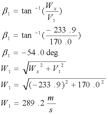
Now we can find the angle B1 that the rotor blades should be positioned at. To do this, we use simple geometry from the velocity triangle. Once the blade inlet angle has been found, we can find W1 which is the velocity of the fluid flow relative to the rotor blade. This is done by applying the Pythagorean theorem to the velocity diagram above.
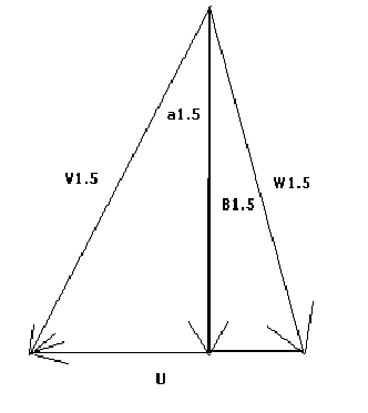
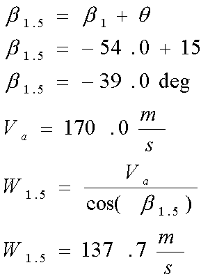
Once these values are known, we can find the angle that the flow leaves the rotors at. The rotor blades are not straight but are instead curved from the base to the tip. The blade is "bent" through what is known as a turning angle. Essentially, the rotor turns the air through some angle, theta.. Assume for this case that the turning angle is 15 degrees. Thus, the fluid will leave the rotor blade at the angle B1.5 , which is the sum of the rotor inlet angle and the turning angle. Using the above velocity diagram, the relative velocity of the fluid leaving the rotor can be found. Again, this is a simple geometry problem since cos(B1.5) = Va/W1.5. Note that the actual fluid velocity (Va) does not change but remains a constant throughout the process.
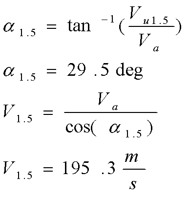
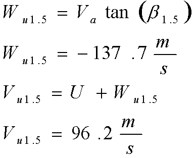
Next, we need to find V1.5, which is the velocity that the fluid leaves the blade at. To do this however, we need to find other parameters first. We must first determine the component of the relative velocity in the x direction (Wu1.5), then use that to find the actual velocity that the fluid leaves the rotor at in the x direction (Vu1.5). Then we need to find the angle that the fluid enters the stator at (alpha1.5), in order to find the actual velocity of the fluid coming off of the rotor blade (V1.5). From the geometry of the velocity triangle below, Wu1.5 can be found. Then, Vu1.5 is the vector addition of the relative velocity in the x direction with the rotor velocity.
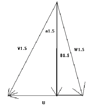
Next, we use Vu1.5 to find the angle that the fluid enters the stator at. Again, this is a problem of simple geometry using the above velocity diagram. This is shown in the equation below. Knowing the inlet fluid velocity and now also alpha1.5, the velocity that the fluid leaves the rotor at (V1.5) can be found.
