|
|
|
Cheryll Hawthorne |
|
Supervised by Dr. Alvi |
|
EML 4421 |
|
09 Nov 01 |
|
|
|
|
|
Subsonic Inlets |
|
Flow Patterns |
|
Internal Flow |
|
External Flow |
|
Inlet Performance Criteria |
|
|
|
|
|
|
|
Supersonic Inlets |
|
Reverse Nozzle Diffuser |
|
Shock Boundary Layer Problem |
|
External Deceleration |
|
Flow Stability Problem |
|
|
|
|
|
|
Prevent boundary layer separation |
|
Lower sensitivity to pitch and yaw |
|
Minimize stagnation pressure loss |
|
Produce uniform flow velocity and direction |
|
Increase efficiency operation in both supersonic
and subsonic |
|
Reduce flow distortion at engine fan face |
|
Increase pressure recovery |
|
|
|
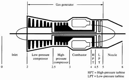
|
Inlet-sucks in air |
|
Compressor-squeezes the air |
|
Combustor-adds heat to the air |
|
Turbine-provides work for the squeezing process |
|
Nozzle-blows the air out the back |
|
|
|
|
|
|
|
|
Sucks in air |
|
Slows air down |
|
Feeds air into compressor and fans |
|
|
|
|
Subsonic |
|
Supersonic-use shock wave to slow down air |
|
|
|
|
|
|
Turbojet |
|
Turbofan |
|
Afterburning Turbofan |
|
Turboprop/ |
|
shaft |
|
|
|
Ramjet |
|
Scramjet |
|
Turbojet/Ramjet |
|
|
|
|
|
|
Ramjet |
|
Scramjet |
|
Turbojet/Ramjet Combo |
|
|
|
|
|
|
|
Ramjet |
|
Incoming high speed air |
|
Compressed by ram effect |
|
For high enough air speed, no compressor or
turbine needed |
|
|
|
|
|
|
|
Scramjet |
|
Supersonic Combustion Ramjet |
|
Air mixed with fuel while traveling at
supersonic speeds |
|
Temp increase and pressure loss due to shocks
are greatly reduced |
|
|
|
|
|
|
|
Pulse Jets |
|
Series of spring-loaded shutter type valves
before compressor |
|
Valves close to prevent backflow |
|
|
|
|
|
|
|
Pressure and/or velocity flow distortions at
engine (compressor) fanface can compromise engine efficiency. |
|
Separation of incoming boundary-layer flow can
reduce pressure recovery and lead to: |
|
Unsteady loading |
|
Increased fatigue of engine fan blades |
|
Aerodynamic stall on compressor blades1 |
|
|
|
|
|
|
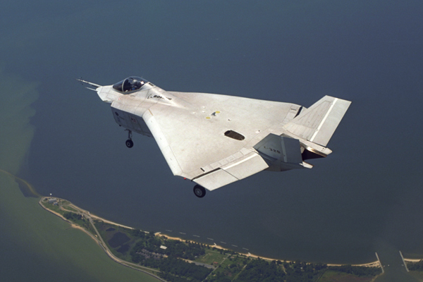
Joint Strike Fighter |
|
|
|
|
|
|
|
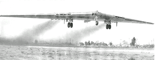
NASA/Boeing, Blended Wing Body |
|
|
|
|
|
|
|
|
Engine inlets located at the aft end of aircraft |
|
Developing large boundary layer upstream of
engine inlet |
|
|
|
|
|
|
|
|
|
|
Inlet operates with a wide range of incident
stream conditions |
|
due to flight speed and the mass flow demand by
the engine |
|
|
|
|
chosen to minimize external acceleration during
takeoff |
|
Upstream area is less than inlet area |
|
|
|
|
|
|
Stagnation Temperature |
|
T02=Ta(1+M2(k-1)/2) |
|
|
|
Stagnation Pressure |
|
P02=pa(1+nd(T02/Ta)-1))kd/(kd-1) |
|
nd=adiabatic diffuser efficiency |
|
|
|
|
|
Behaves as though in a diffuser |
|
Momentum decreases |
|
Pressure rises |
|
No work |
|
|
|
|
|
|
Inlet area often chosen to minimize external
acceleration during takeoff |
|
So that external deceleration occurs during
level-cruise operation |
|
External deceleration requires less internal
pressure rise |
|
Hence, less severe loading of the boundary layer |
|
|
|
|
|
|
|
Flow in the inlet behaves like a diffuser or
decelerator |
|
Inlet design depends on: |
|
Potential flow calculations |
|
Boundary layer calculations |
|
Wind tunnel testing to assess inlet performance
under a wide range of test conditions |
|
|
|
|
|
Separation may take place in 3 zones |
|
External flow zone |
|
Along underside of internal flow zone |
|
Along upperside of lower wall of internal flow
zone |
|
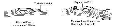
At high angles of attach, all three zones could
be subjected to unusual pressure gradients |
|
|
|
|
Inlet design requires a compromise between
external and internal deceleration to prevent boundary layer separation |
|
|
|
|
|
|
Subsonic flow over inlet lip |
|
High velocity causes low pressure region
followed by high pressure region |
|
Causing boundary layer separation |
|
|
|
|
Supersonic flow usually ends in abrupt shock |
|
Shock wall intersection may cause boundary layer
separation |
|
|
|
|
|
For strong shock wave |
|
M>1.25 |
|
Large pressure gradient near wal |
|
Fluid near wall cannot move in main direction |
|
Boundary layer separates |
|
|
|
|
Results in poor pressure recovery in the flow |
|
Causing extra rearward drag on the body |
|
Decreasing efficiency |
|
|
|
|
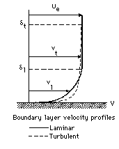
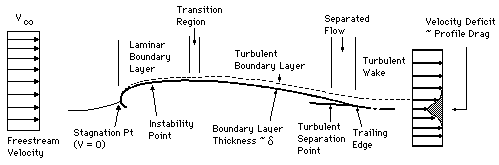
Boundary layers
separate from a body due to increasing fluid pressure in the
direction of the flow (adverse pressure gradient) |
|
Increase in the fluid pressure increases
potential energy of the fluid |
|
kinetic
energy decreases |
|
Fluid slows and boundary layer thickens |
|
Wall stress decreases and fluid no longer
adheres to the wall |
|
|
|
|
|
|
2Boundary layers occur on surface of
bodies in viscous flow |
|
|
|
|
|
|
|
|
large increase in drag on the body |
|
Flow distortions |
|
|
|
|
|
|
|
|
|
Passive |
|
Uses vortex generators |
|
|
|
Supersonic microjets |
|
|
|
Enhance flow uniformity |
|
|
|
Boundary layer fluid is energized |
|
|
|
|
|
|
|
Drawback |
|
Performance is not uniform over entire engine |
|
Possible Solution |
|
Use large number of generators in inlet ducts |
|
Consequence |
|
Additional pressure loss |
|
|
|
|
|
|
|
|
active flow control scheme |
|
|
|
with feedback control |
|
|
|
Leads to reduced distortion over large
parametric range |
|
|
|
|
|
|
In zone 1 due to local high velocities and
deceleration over outer surface |
|
In zone 2 or zone 3 depending on the geometry of
the duct and the operating conditions |
|
|
|
|
|
|
|
Depends on the pressure gradient on both
internal and external surfaces |
|
External pressure rise is fixed by: |
|
external
compression |
|
Ratio of Area Max |
|
Area Inlet |
|
Internal pressure rise depends on the reduction
of velocity |
|
between entry to the inlet diffuser and entry to
compressor |
|
|
|
|
Isentropic Efficiency |
|
Stagnation pressure ratio |
|
|
|
|
|
|
|
|
|
|
Flow leaving inlet system must be subonic |
|
Fully supersonic stream would cause excessive
shock losses in compressor |
|
Mach number for flow approaching subsonic
compressor: Mmax=0.4-0.6 |
|
|
|
|
|
|
4<M<6 |
|
approaching a subsonic compressor |
|
|
|
|
No Mach # limitations for RAMJET |
|
SCRAMJET – supersonic combustion ramjet |
|
However, no application to date in flight
vehicle |
|
Causes excessive aerodynamic loss |
|
|
|
|
The Starting Problem |
|
The Shock-Boundary Layer Problem |
|
Flow Stability Problem |
|
|
|
|
Internal supersonic deceleration in a converging
passage of nonporous walls is hard to establish |
|
Current solution-overspeeding the inlet air or
varying the diffuser geometry |
|
|
|
|
Wall boundary layer may cause strong shocks |
|
A disastrous effect on duct flow |
|
Large shocks may require 10 duct widths or more
to return to uniform flow |
|
|
|
|
|
|
|
Oblique shock - produces less pressure rise |
|
Create shock near thinnest part of boundary
layer |
|
|
|
|
|
|
Subcritical-spilling of flow and normal shock
upstream of inlet |
|
Critical-differs only in the amount of spillage |
|
Supercritical-normal shock occurs at a higher
Mach # |
|
|
|
|
Different geometries under testing |
|
However, diverters create additional drag |
|
|
|
|
Shorten inlet lengths-reduce flow separation |
|
Vortex generators-energize boundary layer |
|
|
|
|
Reduce flow distortion by redistributing energy |
|
But performance of control devices not uniform
over entire area |
|
Need large number of devices to achieve uniform
performance |
|
|
|
|
Use supersonic microjets to reduce distortion
over large parametric range |
|
Grid of supersonic microjets installed in ramp |
|
Microjets placed at curve of ramp where
separation is assumed |
|
|
|
|
Mean and unsteady surface flow properties are
monitored near boundary layer separation |
|
Unsteady surface pressures measured with high
frequency miiature pressure transducers |
|
Visualization techniques |
|
|
|
|
Mean, total pressure contours obtained in cross
planes at selected streamwise locations |
|
Contours represent effect of microjets on steady-state distortion and total
pressure recovery |
|
Measure pressure fluctuations above ramp to
characterize dynamic distortion |
|
|
|
|
Subsonic wind tunnel |
|
Initial tests will later be used to develop
supersonic tests |
|
|
|
|
Active
Control of Boundary-Layer Separation & Flow Distortation in adverse
Pressure Gradient Flows via Supersonic Microjets, proposal to NASA Langley
Research Center, Farrukh Alvi |
|
http://www.desktopaero.com/appliedaero/blayers/blayers.html |
|
http://www.aircraftenginedesign.com/abefs.html |
|
Alvi, Elavarasan, Shih, Garg, and Krothapalli,
“Active control of Supersonic Impingin Jets using Micro Jets, AIAA
2000-2236, submitted to AIAA Journal |
|
|
|
|
|

 Notes
Notes