Exhaust theory
Exhaust Characteristics
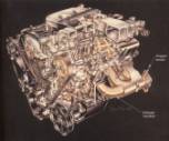
On the other side of the engine another manifold is connected to assist with the exhausting of the noxious gasses left over from the combustion of the fuel and air. This exhaust manifold is equally important in its design to help achieve the proper breathing of the IC engine.
The exhaust system consists of the exhaust manifold,
the header, the catalytic converter, the muffler, and the tailpipe. For all
theoretical considerations, the important aspects occur before the header,
since after this point, the reflected waves are of little relevance because of
their low magnitude. This is due to the length of pipe they must travel to then
come back as reflected waves.
Exhaust theory
The exhaust system is a relatively simple system to
analyze. Certain flow characteristics must be met for the optimal performance of
the exhaust system. One such characteristic is a low backpressure, since the
flow should be as smooth as possible. This entails a free flowing muffler and
catalytic converter. Another
consideration for the exhaust comes from an energy conservation standpoint. Here the exhaust wants to lose as little
heat to the outside of the exhaust pipe so that the charge of the exhaust
gasses will stay at a constant velocity and not slow down creating a back
pressure. As stated above this would
have a detrimental effect on the manifold system and can be seen in the use of
stainless steel or ceramic coated headers that will retain this valuable heat.
The exhaust can be designed to give the best tuning
results in accordance to the previous discussion on intake theory. Taking
advantage of the pressure phenomenon allows the engine to breathe better by
assisting in the removing of toxic gases from the combustion chamber. One such exhaust manifold configuration is
the 4-2-1, which means four pipes to two pipes to one pipe. Here the exhaust
pressure pulse travels down the exhausting cylinders pipe and reflects back
down the other pipes creating expansion and compression waves. When tuned properly to the engine the
reflected waves will reach the exhaust valves at the last possible moment to
pull out the gasses from the exhausting cylinder by way of an expansion
wave. This situation repeats over and
over due to the firing order of the pistons.
Another is the 4-2, and even a 4-1-2 configuration, all designed for the
specific engine to give maximum output from the exhaust, with regards to
pulses.
 However for the consideration of the manifold design only the
portion to just after the manifold itself is used. Once again the shape and size of the manifold become dependant on
the objectives of a particular engine.
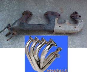
For most engines a simple cast iron manifold is used due to cost and
manufacturability. This technique is
valid for most production manifolds; yet there has been a large push in recent
year to tune the manifold and hence changing the name of it to a header. The push toward the design of a header have
been motivated by an increase in demand for a performance engine and also in
trying to optimize the engine itself lending to more stringent emissions
standards. As mentioned above, for an
optimal exhaust system you want to create as little backpressure as possible.
Doing this will enhance flow of air and not let any of the exhaust gases flow
back into the cylinder creating backflow.
To achieve this small amount of flow a large free flowing muffler is
desired as well as using a piping system with minimal bends thus eliminating
all sources of loss possible.
However for the consideration of the manifold design only the
portion to just after the manifold itself is used. Once again the shape and size of the manifold become dependant on
the objectives of a particular engine.
For most engines a simple cast iron manifold is used due to cost and
manufacturability. This technique is
valid for most production manifolds; yet there has been a large push in recent
year to tune the manifold and hence changing the name of it to a header. The push toward the design of a header have
been motivated by an increase in demand for a performance engine and also in
trying to optimize the engine itself lending to more stringent emissions
standards. As mentioned above, for an
optimal exhaust system you want to create as little backpressure as possible.
Doing this will enhance flow of air and not let any of the exhaust gases flow
back into the cylinder creating backflow.
To achieve this small amount of flow a large free flowing muffler is
desired as well as using a piping system with minimal bends thus eliminating
all sources of loss possible.
