Linear Aerospike Engine
The aerospike engine is recent advancement in rocket engine technology. Initially designed as a means of propulsion for the SSTO (Single Stage to Orbit) X-33 being developed by Lockheed-Martin, it has since been placed aside due to the cancellation of the X-33 program. The technology developed though is now being considered for use in the next generation of the space shuttle. The primary advantage of the linear aerospike engine is that it is optimal at all atmospheric pressures, that is, there is no thrust loss to the engine during flight, removing the need for different nozzles.
The linear aerospike engine is different from the conventional bell nozzle in that it does not constrain one side of the exhaust plume allowing it to freely expand to optimal performance. The shape of the engine is seen in figure 4.
Figure 4
The exhaust from the nozzle is aimed at a ramp, which assists in the expansion of the exhaust. The aerospike offers other advantages as well. The engine is 75% shorter than the current nozzles used, it is also lighter and can fit into the RLV’s (reusable launch vehicle) airframe quite easily which reduces drag making the entire rocket more efficient. Figure 4 shows a side view of the whole engine configuration. The actual engine consists of multiple nozzles in a linear array as can be seen in the test firing of the engine in Figure 5.
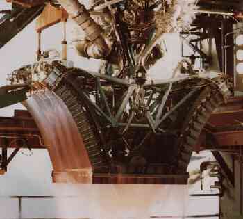
Figure 5.
The Space Shuttle main engines are attached to gimball machines that allow the engines to be moved to produce thrust vectoring. This system is very high maintenance and must be carefully inspected after each flight and replaced often. The linear aerospike configuration allows for easy thrust vectoring without any such devices. Figure 6 shows the different configurations on how thrust vectoring can be achieved.
|
|
|
|
Figure 6
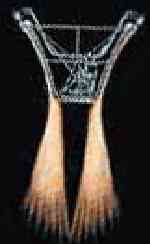
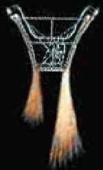
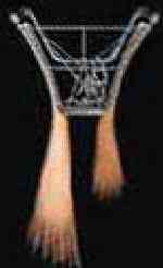
Figure 6-1 shows neutral thrust, which gives no rotation to the shuttle, 6-2 has a stronger thrust on the right which rotates the ship counter clockwise, and 6-3 does the exact opposite. Also because of the linear configuration, the thrust can be varied along the line of thrusters in order to control yaw. This is a highly efficient method due to the ease by which it is achieved. Figure 7 demonstrates the difference in plume sizes at different heights. Close to sea level the plume is very narrow, higher up the plume expands to a very large exhaust area.


Figure 7
Figures 8 and 9 show a detail of how the aerospike engine expands the plume to atmospheric pressure. In figure 8, expansion waves help to expand the plume outward, but a compression wave reflecting from the ramp keeps the plume from expanding beyond atmospheric pressure, this process continues until the plume leaves the nozzle, and is properly expanded to atmospheric pressure. Figure 9 views the nozzle at a height where the atmospheric pressure is at a minimum. In this case no compression waves adjust the pressure of the exhaust plume, rather expansion waves expand the plume to atmospheric pressure. When the gas leaves the nozzle it is optimally expanded.
Figure 8
Figure 9
As can be seen two expansion waves are produced at the nozzle exit which cause the plume to move outward creating a large plume at higher altitudes. There is no flow separation along the nozzle because no adverse pressure gradients exist. The pressure is always greater than atmospheric along the nozzle. At low altitudes the compression waves keep the pressure from dropping too low, while at higher altitudes the expansion wave doesn’t touch the nozzle until the very end.
Over 4,000 seconds of test firings have been done which represent almost 11 flights into space (though the actual launch vehicle hasn’t been used). Though the technology has been proven for the engine, materials and other related problems for the construction of an SSTO has caused the program to be placed on wait
Other Related Sites: