Valve Design and VVT Presentation
Valve Design and
Variable Valve Timing Systems
Introduction
This site discusses valve design in internal combustion engines. It also discusses techniques to increase engine performance by changing valve numbers and timing. Please follow the links above and below to learn more about engine valves.
Above is a very simple drawing of a valve. The important dimensions of a valve are shown. Below in a picture of so actual valves.
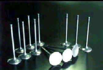
The valves are located at the top of the cylinder. The valves open to allow air and fuel into the engine during the intake stroke. Then, during the exhaust stroke another valve opens to allow the combusted air to leave the cylinder.
An engine only needs to have one intake and one exhaust valve to function. Many engines however use multiple valve designs.
Click HERE to find out more about multiple valve technology.
Valves are held in place by springs shown below.
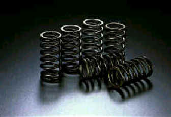
The spring hold the valve in place and provide the force needed to close the valve.
The engine cams open the valves. The cam is shown below in orange. It is driven by the engine and pushes up on a rocker arm shown in blue. This in turn pushed the valve down allowing it to open.
By changing the when the valves open and close the engines performance can be increased. To find out more follow the links below.
Click HERE to find out the benefits of Variable Valve Timing.
Click HERE to take a look at some Variable Valve Timing Systems in use today.