Inkjet Droplet Injection Process |
||
|
Injection process-still images
|
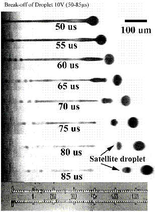
The following animated sequence shows the liquid ink column is ejected out of a HP printhead nozzle and begins to form a primary ink droplet. The existence of a very long tail and the emergence of the Raleigh jet instability force the narrow jet column to break up into several satellite droplets. The presence of satellite droplets can significantly degrade the printing quality of an inkjet printer.
Injection Process, Still Images
The time associated with each droplet image indicates the dalay in ms between the time when the picture is taken and the time when the electric current pulse is activated. Photograph courtesy of Dr. Fan-Gang Tseng.
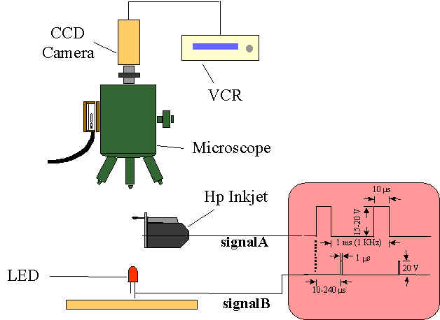
Schematic of the droplet visualization setup, courtesey of Dr. Fan-Gang Tseng. The droplet injection process is visualized using a digital CCD camera via a microscope system as shown. A phase-triggered LED is used to backlite the process. A very short duration electric pulse is sent to the printhead to initiate the injection process at a frequency of 1 kHz. It can be seen from the above animated sequence that the jet column experiences instability and breaks up into a stream of small satellite droplets following the primary droplets. The existence of these small droplets can significantly lower the inkjet printing quality since they have different trajectories from the primary one. As a result, they will fall on different locations from that of the primary droplet (as shown below).
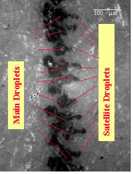
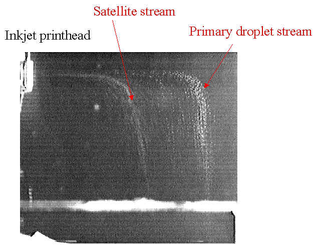
Sample line inkjet printing from a HP printhead, showing the primary and the satellite droplets. Consequently, the printing resolution (as usually characterized by the dots per inch (DPI)) is degraded. The trajectories of these droplets can also be visualized using a CCD video camera. It is clear from the following inkjet injection photograph that the satellite droplet stream has a different trajectory from that of the primary droplet stream.
Inkjet injection process of a HP printhead. The above photograph shows the inkjet injection process as the droplet streams coming horizontally out of a HP inkjet print head. The ink droplets experience aerodynamic drag and gravitational pulling force when they are exiting from the nozzle. Since the droplets are relatively small (of an order of 50 mm in diameter), the Stokes' drag law is valid for the description of the drag on the droplets. Note: this is not true initially when the droplet velocity is high (of an order of 10 m/s), however, the velocity decreases very fast and the Stokes' law can be applied shortly after the droplet velocity decelerates. It is interesting to note that the droplet trajectory takes a very steep turn as the droplets lose their speed. Also, the satellite droplets follow totally different trajectories as they fall down earlier as compared to the primary. This is mainly due to the relatively lower speed of the satellite droplets.
|
|


